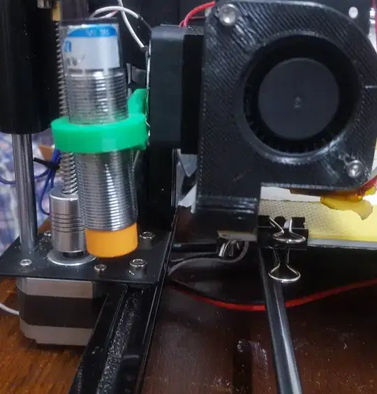
It is not a problem that the sensor is not above the build plate during printing as long as it is above the build plate during the auto bed levelling sequence.
Homing does not necessarily need to be the (0,0) coordinate. Usually, a printer homes on the endstop switches, from that coordinate an offset is defined in the firmware to move to the origin. This implies that (depending on the position of the sensor), the sensor may be outside the bed area when the nozzle is at the origin (0, 0)). Therefore, similarly, you need to tell the printer the location of the Z sensor with respect to the nozzle position in order for the printer to keep the sensor on the bed when levelling by setting boundaries for the sensor to reach.
E.g. for Marlin firmware the offset from homing to the bed origin is defined for an Anet A8 by:
#define X_MIN_POS -33
#define Y_MIN_POS -10
The values you should use need to correspond to the actual offset from the homing point to the origin of the bed (0,0).
When using an auto bed leveling sensor like you are using you should consider this remark:
If using a Probe for Z Homing, enable Z_SAFE_HOMING also!
Un-comment the proper line in the configuration file to read:
#define Z_SAFE_HOMING
This will make the printer aware of the sensor, and home Z in the middle of the bed (default behavior, but can be changed), so that your sensor is never off the bed when probing the bed for Z homing.
Furthermore, you need to set the offset values of the center of your sensor to the nozzle center:
 *   Z Probe to nozzle (X,Y) offset, relative to (0, 0).
 *   X and Y offsets must be integers.
 *
 *   In the following example the X and Y offsets are both positive:
 *   #define X_PROBE_OFFSET_FROM_EXTRUDER 10
 *   #define Y_PROBE_OFFSET_FROM_EXTRUDER 10
 *
 *      +-- BACK ---+
 *      |           |
 *    L |    (+) P  | R <-- probe (20,20)
 *    E |           | I
 *    F | (-) N (+) | G <-- nozzle (10,10)
 *    T |           | H
 *      |    (-)    | T
 *      |           |
 *      O-- FRONT --+
 *    (0,0)
 */
#define X_PROBE_OFFSET_FROM_EXTRUDER XXX   // X offset: -left  +right  [of the nozzle]
#define Y_PROBE_OFFSET_FROM_EXTRUDER YYY   // Y offset: -front +behind [the nozzle]
#define Z_PROBE_OFFSET_FROM_EXTRUDER 0   // Z offset: -below +above  [the nozzle]
Where XXX and YYY are your actual values.
And set the boundary of the probing section:
// Set the boundaries for probing (where the probe can reach).
#define LEFT_PROBE_BED_POSITION 15
#define RIGHT_PROBE_BED_POSITION 190
#define FRONT_PROBE_BED_POSITION 15
#define BACK_PROBE_BED_POSITION 170
Note that the values should match your bed size!
And:
// The Z probe minimum outer margin (to validate G29 parameters).
#define MIN_PROBE_EDGE 10
Details on setting the boundaries of the bed to keep the sensor on the bed is described in question "How to set Z-probe boundary limits in firmware when using automatic bed leveling?".
