2

I'm currently attempting to make a repstrap using paper printed parts, like this guy : http://www.mariolukas.de/2012/05/repstrap-3d-drucker-aus-computerschrott-teil-1/ I replaced the DC motor in a paper printer carriage assembly

with a stepper motor (NEMA17). But there was not enough space to fit the axis of the nema 17 at the exact spot of the older DC motor axis, in short, the axis are not in the same place. The question is : if the axis is not in the exact same spot, will it affect the movement of the carriage or not at all ?new and old belt driven axis

I supposed it would but i'm not sure since the carriage is limited in movement by the rails and that we still move the belt around.
2 Answers2

3

Axis should definitely be at proper position. Otherwise you will get at least 2 issues.

  1. Carriage will be pulled up which will cause stresses on rollers or slides and it will stress your belt
  2. The way the carriage will go will change but because carriage itself is fixed then it will change the speed

3D printing is a precise process. Both issues will have impact on printouts and all your printouts will have broken dimension in the axis in which carriage moves.

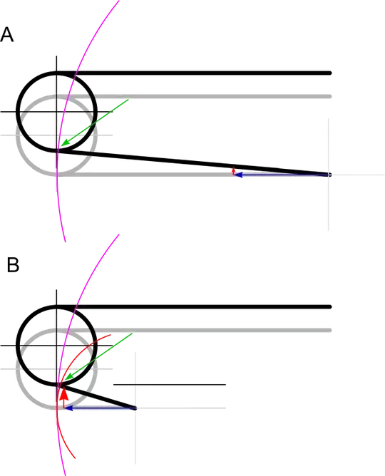
Have a look on the picture (it is big to show details)

enter image description here

fig A shows a situation where carriage is far from the axis

In such situation the distance between vertical line of black cross and pink circle is almost unnoticable so both - the force and the distance (so speed) change are very small.

fig B shows a situation where carriage is relatively close to the axis

Then both - the force and the distance change is noticable

darth pixel
  • 3,438
  • 1
  • 11
  • 20
  • Thanks so much for that precise comment, but I gotta say I exaggerated a lot on the paint picture. The distance between the original shaft and the new stepper motor shaft is probably about 5mm or so. I suppose the print problems is of course dependent of the distance between the shafts so maybe if the distance is small, the problems are not noticeable (I hope so) ? – Blunderboss Aug 19 '16 at 10:53
  • The higher difference in position the bigger effects. But the issue is that this "error" in not constant - it changes while carriage moves. It means your printouts will also be distorted non linear... But please remeber - 3D printing is preise process. Half milimeter is usually 2 times nozzle diam. – darth pixel Aug 19 '16 at 11:06
  • Damn, building a 3d printer from scratch is really hard... Thanks again for your answers. – Blunderboss Aug 19 '16 at 11:11
0

A rotation of the stepper motor 90 degrees clockwise or counter-clockwise would move it more to the center. You would only need lengthen or shorten the belt.

spicetraders
  • 278
  • 1
  • 7
  • according to my experience the most of stepper motors (especially those used in cheap or home made) in 3D printers have rectangular shape and the shaft in in the center (precisely). As an exception I can pint geared stepper motors but I suppose it's not the issue here. So What do you mean by "rotation would move it to the center"? – darth pixel Aug 25 '16 at 09:28
  • As you state most are square with four point mounting shaft in center. Not knowing how the offset shaft motor is mounted can only expect it is four point or two point or clamp. But should be able to unbolt from the mounting plate and rotate the whole motor on the shaft axis. – spicetraders Aug 25 '16 at 15:21
  • He said - no room, which means for me - no room. – darth pixel Aug 25 '16 at 15:35
  • I understood no room was for changing stepper to a different one. Not from rotation of existing. – spicetraders Aug 25 '16 at 16:36
  • 5 min limit edits What I was trying to say is the large circle the chassis or the stepper. If it is the stepper then why no rotation, if it is the chassis then I understand the shaft is stuck to top of chassis and only option is a different smaller stepper. – spicetraders Aug 25 '16 at 16:42