5

I'd like to add an extra motor to my board and I'm not sure where I went wrong. The motor will be used to spin a rotating wheel/carriage of potential hot ends to switch to. Because it's just a motor it doesn't need a heatrod or a temperature sensor.

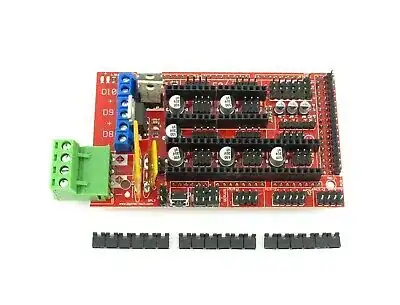
I had just a MKS_BASE 1.0 board, so I purchased a RAMPS 1.4 board from Ebay to be its extender.

RAMPS 1.4 board

(( **Warning ** this board is cheap because it was improperly produced and is a fire hazard: https://reprap.org/wiki/RAMPS_1.4 . I recommend using a CNC shield instead ))

This red board is meant to fit an Arduino Mega, but I figure I can use the extra pins on the MKS_BASE1.0 and connect them with jumper wire to the RAMPS 1.4 board. It made sense in case I want to add other things to the original MKS_BASE 1.0 board (like more hot end heater cartridges).

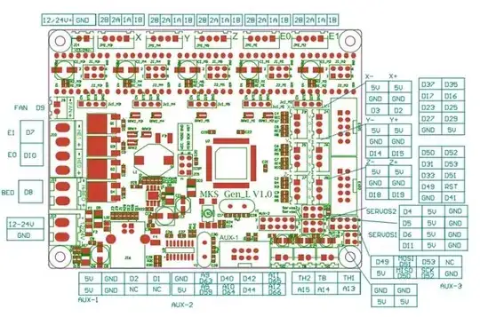
I connected the 5V and one GND pin from my MKS_BASE 1.0. I also connected some of the SERVOS pins from the MKS_BASE 1.0: D37 is the 'Dir', D35 is the 'Step', and D17 is the 'Enable'. I also connected the 12V power supply to the RAMPS 1.4 board too.

RAMPS 1.4 board pinout

When it came time to modify Marlin everything was a bit annoying because although Marlin makes it easy to add more extruders, adding just motors is a little more difficult. I had to change the number of extruders to be 3 (from dual extrusion to dual extrusion + extra motor), enable an extra temperature pin (which i am leaving empty) and also modify the pins.h file.

I probably wouldn't have had simulate this motor as an extruder if I knew the raw Arduino commands for spinning a motor using calls to D37, D35, and D17, so I figured simulating an extruder would be better, but now I'm second-guessing that decision.

Here's my modification to pins.h:

#define E2_STEP_PIN 35
#define E2_DIR_PIN 37
#define E2_ENABLE_PIN 17

#define HEATER_2_PIN 17  

//#define TEMP_SENSOR_2 3 in Configuration.h

#define TEMP_2_PIN 3

// Marlin 0-indexes these pins, so "2" is actually for the "3"rd extruder

First thing I have to do is allow for cold extrusions by using M302 S-80. The other (real) extruder motors will all move after this command, so I have that part working.. .

In Repetier-Host I am just selecting Extruder 3 and trying to "push filament" through it but the motor isn't moving. I'm using an A4988 stepper driver on a Kysan 1124090. Actually, I did this whole process with two motors because I wasn't sure whether the hardware itself would be an issue, so with another set of pins I'm using a Suncor Motor and it also doesn't respond and I also don't know why.

It would be really helpful to debug if I could run a single G-code command just to get the motor running at a speed, and take that out of the equation. it doesn't have to be a command to an "extruder" but just a command to a pin out, like M42 D35 S100 (but I don't know the raw command for just testing a motor's connections).
K Mmmm
  • 1,600
  • 11
  • 30

2 Answers2

2

D35, D37, D17 are the pin labels on the Arduino Mega. These do not correspond to pin numbers within Marlin.

I believe that D35 actually corresponds to marlin pin 49 and this is the number you should enter in your firmware. You can find the mapping in fastio_1280.h:

Hardware Pin  : 02 03 06 07 01 05 15 16 17 18 23 24 25 26 64 63 13 12 46 45 44 43 78 77 76 75 74 73 72 71 60 59 58 57 56 55 54 53 50 70 52 51 42 41 40 39 38 37 36 35 22 21 20 19 97 96 95 94 93 92 91 90 89 88 87 86 85 84 83 82 04 08 09 10 11 14 27 28 29 30 31 32 33 34 47 48 49 61 62 65 66 67 68 69 79 80 81 98 99 100
Port          : E0 E1 E4 E5 G5 E3 H3 H4 H5 H6 B4 B5 B6 B7 J1 J0 H1 H0 D3 D2 D1 D0 A0 A1 A2 A3 A4 A5 A6 A7 C7 C6 C5 C4 C3 C2 C1 C0 D7 G2 G1 G0 L7 L6 L5 L4 L3 L2 L1 L0 B3 B2 B1 B0 F0 F1 F2 F3 F4 F5 F6 F7 K0 K1 K2 K3 K4 K5 K6 K7 E2 E6 E7 xx xx H2 H7 G3 G4 xx xx xx xx xx D4 D5 D6 xx xx J2 J3 J4 J5 J6 J7 xx xx xx xx xx
Logical Pin   : 00 01 02 03 04 05 06 07 08 09 10 11 12 13 14 15 16 17 18 19 20 21 22 23 24 25 26 27 28 29 30 31 32 33 34 35 36 37 38 39 40 41 42 43 44 45 46 47 48 49 50 51 52 53 54 55 56 57 58 59 60 61 62 63 64 65 66 67 68 69 xx xx xx xx xx xx xx xx xx xx xx xx xx xx xx xx xx xx xx xx xx xx xx xx xx xx xx xx xx xx

Look on the top row for the pin number (e.g. D35 corresponds to 35), then look on the bottom row to find the pin number to use in Marlin (in this case, 49).

Tom van der Zanden
  • 14,588
  • 2
  • 33
  • 60
  • I don't think this is true because the `D` numbers I refer to are from the MKS_BASE1.40 board not the Arduino mega (see second image). When I plug in a pan to pin 49 in the second image and run it with `M42 P49 S100` it spins so the Marlin numbers are corresponding to the numbers i'm using. – K Mmmm Jul 22 '19 at 13:48
  • 2
    `M42` does some translation of pin numbers which the motor diving code does not do. – Tom van der Zanden Jul 22 '19 at 13:57
  • My CNC shield came today so I wound up foillowing the guide here; https://reprap.org/wiki/Adding_more_extruders#RAMPS_using_CNC_Shield But it doesn't translate the numbers like you suggested... At the same time, I can get my motor to run very slightly (or at least shake) on the price of a button, but it runs "twitchily" and not smoothly. And I don't know how to fix that. – K Mmmm Jul 22 '19 at 19:34
  • I think you might be right and i don't know how to translate the numbers correctly... In the above MKS_BASE I'm using four of the AUX-1 pins (5V, GND, D1, D2). I'm also using D63 in AUX-2. Going by your translation, my PINS.h should be... what? 0, 4, 15, for D1, D2, and D63? When I do this nothing moves as opposed to when I use 2,1,63 it at least moves a little – K Mmmm Jul 22 '19 at 19:42
  • 2
    Since I wrote the answer I linked to, the pin mappings have changed. I will update the answer with the new mappings. – Tom van der Zanden Jul 22 '19 at 19:58
  • It doesn't move at all with 0,4,15 for D2, D1, and D63 .... I'm just using the MKS_BASE circuit from above, not a raw Arduino Mega – K Mmmm Jul 22 '19 at 20:14
  • Also why doesn't the Guide i link to take this into account ? – K Mmmm Jul 22 '19 at 20:20
1
  • I got it to work using a CNC shield. Still haven't figured out the RAMPS 1.4 board.

  • It doesn't work using D1 and D2 inside Aux-1 because they are used in serial communication to an LCD. So every time you send a command over USB, they get clogged. I ended up using ports 4, 5, and 63 and it works perfectly (no pin mapping needed like in other answer).

    #define E4_STEP_PIN    4 // D4
    #define E4_DIR_PIN     5//  D5
    #define E4_ENABLE_PIN  63// D63
0scar
  • 32,029
  • 10
  • 59
  • 135
K Mmmm
  • 1,600
  • 11
  • 30