6

I am trying to resolve this for months and have tried almost everything, I guess.

I am using Marlin firmware on a custom extruder with a custom fabricated heating block in which heater and thermistor (Marlin Temp_Sensor 11) are set up perpendicular to each other. Whenever I try to heat it up to 200 degree Celsius, it falls short and fails at around 140 and that too with a very low pace (especially between 100 to 140).

I have already tried PID tuning, ADC values calibration, etc. Also, I have tried varying the values of Watch_Temp_Sensor in Configuration_Adv.h. I don't know what's going wrong.

Can extruder coldend fan have an effect on the heating of thermal block? I have tried heating the hotend without cooling the coldend, although it takes around 10-12 minutes yet it works perfectly fine then and it reaches to the desired temperature.

The power supply is working fine

P.S. I am not using any kind of pre-built extruder like E3D etc.

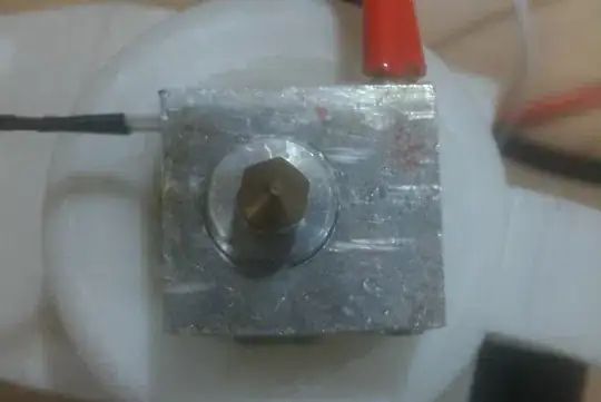
This is the setup:

Photo of hotend

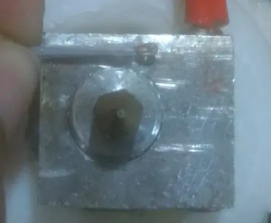
This is the thermistor setup:

Thermistor setup

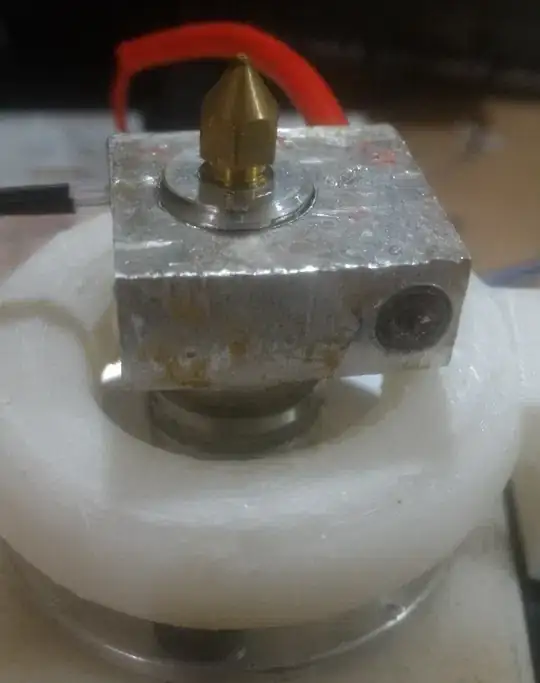
This is a view of heater position:

Heater position

Greenonline
  • 5,831
  • 7
  • 30
  • 60
Yash Soni
  • 61
  • 3
  • The nozzle is screwed into a sort of a heat break I guess, that thing is massively big, isn't that draining a lot of heat out of the heater block into the cold end? And what is that white ring we see? Also post another picture of the side view a little further away, I'm pretty good in reading drawings and constructions, but I miss an overview of the whole hot and cold setup. E.g. what is between the heater cube and mounting screws and what is it screwed on? – 0scar Sep 05 '18 at 20:25
  • [This question](https://3dprinting.stackexchange.com/questions/572/what-is-the-best-length-of-the-melting-zone-in-the-hotend/574#574) may be of interest for you. – 0scar Sep 06 '18 at 10:44

2 Answers2

2

There are many unknowns at this point, you need to work methodically through each stage. You probably also need some test equipment, at least a basic multimeter. Ideally a temperature probe too.

First, check that your power supply can drive the hot-end directly. You already know how long it takes to reach 120°C, so be sure to not let it heat too far beyond this time. This will bypass all of the control logic, and risks overheating your hotend/burning out the heater - but it should be OK if you limit to a few minutes.

Check the temperature reading, and cross check with some PLA or other low melting point filament to see if you actually reach ~180°C. Check the voltage as close to the heating cartridge as you have a connection point. It should be at least 11V (with a 12V PSU). My guess is that you have a bad connection somewhere...

If you observe the hotend getting hot enough to melt plastic, check the thermistor readings. You should see a fairly constant rate of heating well past 200°C. However, I expect this will work fine.

Finally, check the hotend mosfet drive and output as the hotend reaches the target temperature. It should be on, then switching on/off, then off as you pass the target.

If this all looks OK, repeat but with the board in-circuit and controlling the heater. It may be that the mosfet is damaged, or it is not being driven very well - but to progress past that point we need to see voltage readings at various points.

Sean Houlihane
  • 3,712
  • 2
  • 18
  • 39
  • Actually, for being the safe side, I am using the cross-checking PLA technique already. I observed that the region near the heater is fitted is able to melt PLA very fast but if I try to go a bit far, like, where the thermistor is installed, the melting is taking more time. I am doing this by using a strand of PLA and pushing it against the thermal block. Can this be an issue of thermal block insulation? – Yash Soni Sep 04 '18 at 07:44
  • It is made from Aluminium only. – Yash Soni Sep 04 '18 at 07:54
1

Now that we can see the real problem, your heater cartridge doesn't have good thermal contact to the block, and the block does not have good contact to the nozzle.

Where is your heatbreak? You need to perform a basic analysis of the heat flow in your design. Anything that is expected to conduct needs to be clamped, and to have thermal paste. Any connection between hot and cold which is used for mechanical support needs to have minimal cross section, and maybe use materials with poor thermal conductivity.

Example

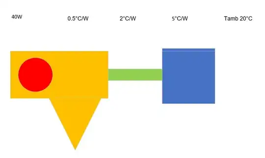
Here is a simplified diagram, with some assumed thermal resistances. Note that the geometry is not representative since your nozzle is actually within the throat, not between the heater and the throat as I've shown.

Heat Flow

Total thermal resistance is 7.5 °C/W. Maximum heat in is 40W, so the heater is at 320°C, and the nozzle can reach 300°C.

Replace the heater with a 20W element, and the nozzle drops to 170°C.

Keep the heater at 20W, to achieve 220° at the nozzle, the throat needs to provide at least 4.5°C/W thermal resistance.

Assuming you're using a 10 mm diameter aluminium bar as a heat break, it needs to be 7 cm long with a 20 W heater. If you use steel instead, the length can be reduced by a factor of about 3.

Sean Houlihane
  • 3,712
  • 2
  • 18
  • 39
  • Don't worry about the nozzle, I have purposely not snugged it. And the through hole in which heater cartridge is fixed is of the same size as the heater cartridge. There is no possibility of moving the cartridge as it is so tightly fitted. Have a look at the thermistor- https://www.amazon.in/3D-Innovations-Thermistor-Pre-Wired-Insulated/dp/B07DCVT7V6, is it the right one or not? – Yash Soni Sep 04 '18 at 11:06
  • we need a side view, what is the other side of the nozzle? – Sean Houlihane Sep 04 '18 at 11:45
  • By the other side, do you mean the opposite side of the third photo? – Yash Soni Sep 05 '18 at 04:25
  • @YashSoni Quick worked example added. – Sean Houlihane Sep 05 '18 at 13:39