4

I had a Z probe installed but the wires came out of the header so I am trying to use software endstops, but any time I G28 the nozzle will always ram into the bed. I am using Marlin Firmware. Which I am relatively new with. I'm used to having hardware endstops, but,

I don't have a hardware endstop currently (no probe/no switch).

  • Is it possible to do this with software?

  • I took out G28/G29 in my G-code and it shows that it is going to z0.2 and working upward (but it still hits the bed). If the bed is level do I need a G28?

  • Should Z probe offset be 0?

    #define USE_XMIN_PLUG
    #define USE_YMIN_PLUG
    #define USE_ZMIN_PLUG
    //#define USE_XMAX_PLUG
    //#define USE_YMAX_PLUG
    //#define USE_ZMAX_PLUG
    #if DISABLED(ENDSTOPPULLUPS)
      // fine endstop settings: Individual pullups. will be ignored if ENDSTOPPULLUPS is defined
      //#define ENDSTOPPULLUP_XMAX
      //#define ENDSTOPPULLUP_YMAX
      //#define ENDSTOPPULLUP_ZMAX
      //#define ENDSTOPPULLUP_XMIN
      //#define ENDSTOPPULLUP_YMIN
      //#define ENDSTOPPULLUP_ZMIN
      //#define ENDSTOPPULLUP_ZMIN_PROBE
    #endif
    #define X_MIN_ENDSTOP_INVERTING true  // set to true to invert the logic of the endstop.
    #define Y_MIN_ENDSTOP_INVERTING true  // set to true to invert the logic of the endstop.
    #define Z_MIN_ENDSTOP_INVERTING true  // set to true to invert the logic of the endstop.
    #define X_MAX_ENDSTOP_INVERTING false // set to true to invert the logic of the endstop.
    #define Y_MAX_ENDSTOP_INVERTING false // set to true to invert the logic of the endstop.
    #define Z_MAX_ENDSTOP_INVERTING false // set to true to invert the logic of the endstop.
    #define Z_MIN_PROBE_ENDSTOP_INVERTING true  // set to true to invert the logic of the probe.

    // Enable this feature if all enabled endstop pins are interrupt-capable.
    // This will remove the need to poll the interrupt pins, saving many CPU cycles.
    #define ENDSTOP_INTERRUPTS_FEATURE
    #define PROBE_MANUALLY
    #define X_PROBE_OFFSET_FROM_EXTRUDER 1   // X offset: -left  +right  [of the nozzle]
    #define Y_PROBE_OFFSET_FROM_EXTRUDER -55 // Y offset: -front +behind [the nozzle]
    #define Z_PROBE_OFFSET_FROM_EXTRUDER -3.4
    #define MULTIPLE_PROBING 2
    #define Z_CLEARANCE_DEPLOY_PROBE   0  // Z Clearance for Deploy/Stow
    #define Z_CLEARANCE_BETWEEN_PROBES  3 // Z Clearance between probe points

    // For M851 give a range for adjusting the Z probe offset
    #define Z_PROBE_OFFSET_RANGE_MIN -20
    #define Z_PROBE_OFFSET_RANGE_MAX 20
    #define INVERT_Z_DIR true
    #define Z_MIN_POS 0
    #if ENABLED(MIN_SOFTWARE_ENDSTOPS)
      //#define MIN_SOFTWARE_ENDSTOP_X
      //#define MIN_SOFTWARE_ENDSTOP_Y
      #define MIN_SOFTWARE_ENDSTOP_Z
    #endif
    #define AUTO_BED_LEVELING_BILINEAR
    #define MANUAL_Z_HOME_POS 0

    #define Z_SAFE_HOMING

    #if ENABLED(Z_SAFE_HOMING)
      #define Z_SAFE_HOMING_X_POINT ((X_BED_SIZE) / 2)    // X point for Z homing when homing all axes (G28).
      #define Z_SAFE_HOMING_Y_POINT ((Y_BED_SIZE) / 2)    // Y point for Z homing when homing all axes (G28).
    #endif
Greenonline
  • 5,831
  • 7
  • 30
  • 60
mlizbeth
  • 143
  • 6
  • 2
    Your question is pretty unclear, I think I understand that you are not using any hardware end stops. How would the printer know where to stop? You need a working mechanical/optical end stop or a some sort of distance sensor. – 0scar Jul 29 '18 at 17:53
  • 1
    What kind of input shall trigger the "Endstop" signal? The new sensor? a switch? The "here is the endstop" signal need to be given somehow. – Trish Jul 29 '18 at 20:11
  • 1
    Thanks! I'm pretty familiar with manufactured bots, but i've never done a DIY kit. I had to rebuild the UM2+/TAZ6/Replicator 2 where I work, fell in love with them and bought my own. But it's never made a successful first layer :( – mlizbeth Jul 30 '18 at 01:10
  • Might be relevant. Please see [this answer](https://3dprinting.stackexchange.com/questions/857/adjusting-the-z-end-stop#answer-859) to [Adjusting the Z end stop?](https://3dprinting.stackexchange.com/questions/857/adjusting-the-z-end-stop) where software stops *are* mentioned – Greenonline Aug 05 '18 at 10:02

2 Answers2

2

There is no such thing as a software endstop for the 3D printer. When you power a printer the print head can be located at every X, Y, Z position (usually, Z is at the print height of your last print, X is at the minimum X, and Y is at an arbitrary location determined by the last print).

This is exactly why we need endstops, either mechanical, optical or electronic (inductive or capacitive) end stop switches or sensors. You instruct the printer to home by using a known fixed location of the printer; this is the hitting of all endstops. The origin of the printer may have offsets, as the origin of the printer may not coincide with the endstop location. For the Anet A6 this is a few millimeters, e.g. for Marlin firmware this is defined in the configuration by:

#define X_MIN_POS -3
#define Y_MIN_POS -5

The answer to your question: "Is it possible to do this with software?" is therefore, no, you cannot do this solely with software.

0scar
  • 32,029
  • 10
  • 59
  • 135
2

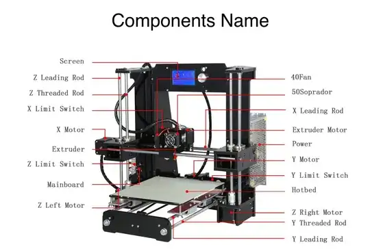
The A6 3D Printer Installation Instruction shows that there is an endstop, part 2-7-2, page 4, included in the kit:

Limit switches

It needs to be fitted as shown on page 8:

Image showing Z-axis minimum stop

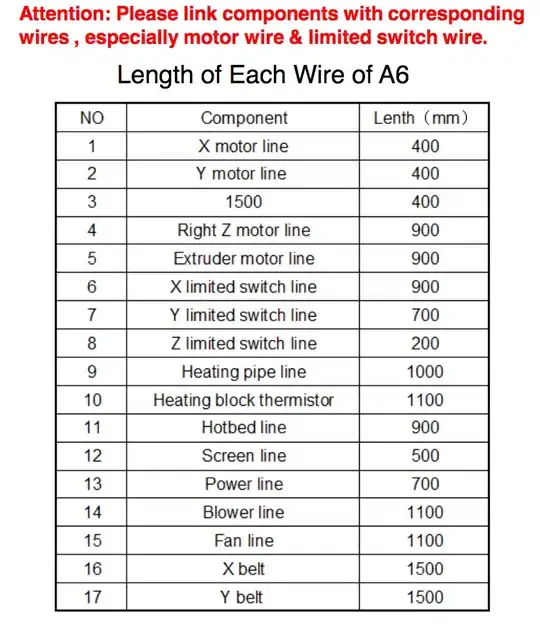
Page 36 shows the correct length of the wires, which should prevent the wires being pulled out of the sensors/switches:

Wire lengths

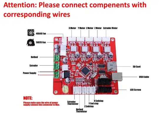
Page 38 shows where the Z-axis endstop is attached to the controller board:

Controller board connections

To be fair, this assembly guide seems to be rather poor quality and after having looked through it a number of times I fail to see any actual instructions on how, or where exactly, to mount the Z-axis minimum endstop.

Greenonline
  • 5,831
  • 7
  • 30
  • 60
  • 1
    I didn't even receive a mechanical endstop switch sadly. That's why I was using a probe, which never worked to begin with either. – mlizbeth Jul 30 '18 at 01:02
  • Hmm, sounds like you should get in contact with the vendor and either get them to send you the missing part or replace the defective parts. Is there a list of parts, or BOM (bill of materials) included in your kit? Did you check the package contents upon arrival? You definitively should have a z min stop at least, and the z-probe as an (optional) extra. If they don't send you one and refuse to help, then all is not lost as endstop switches are cheap ($1-3) on ebay, and printed mounts (in required) are available on thingiverse (generally - I haven't checked for this particular case) – Greenonline Jul 30 '18 at 01:05
  • 1
    I actually think my friend took the endstop when he installed the probe. and the probe doesn't work anymore but that's for another thread. Basically it lights up under metal but M119 always shows it as open where X/Y trigger fine. I'm guessing the signal is not being sent to the board. (And I think that's the case because when I looked that the header for the S_Z, the SIGNAL/GROUND pins weren't in there all the way and the signal wire was frayed, with the pin almost all the way out of the header adapter.) – mlizbeth Jul 30 '18 at 01:09
  • Hmmm, I see. It would probably be worth mentioning all of that in your question. Best to edit the question and add that comment to it. That way all of the information is kept in one central place :-) – Greenonline Jul 30 '18 at 01:11
  • 1
    Fair enough, I just was looking to know if I could force endstops in the software until my replacement endstops arrive :) – mlizbeth Jul 30 '18 at 01:15