G28 instructs the printer to home itself to the X an Y endstops and the Z sensor determines the homing of the Z axis; i.e. when the sensor triggers, this is not necessarily (and most commonly) not the position where the nozzle is at Z=0.
G29 determines the shape of the bed by probing the bed. This will set the shape of the bed with respect to the sensor trigger point as described earlier. The Z-offset (set by M851 Z-x.xx is needed to set the offset between the nozzle and the sensor trigger point (to the bed).
The sequence to determine the offset is:
M851 Z0; // Set the Z offset to zero height
G28;     // Home Z in the middle of the bed
G1 Z0;   // This will move the head to zero height;
M211 S0; // This will disable the end stops so that you
         // will be able to proceed lower than Z=0
Now adjust Z height to fit a piece of paper and note the negative Z height (either through the LCD or through an application or console/terminal over USB)
Please remember, that a sensor doesn't level your bed, is compensates for the shape, the user should always tram (level) the bed as good as possible with respect to the nozzle print head movement plane! This implies that the user should tram the complete bed as good as the skills allow, all corners, like you would do with a normal Z endstop switch.
M851 Z-1.23; // Define the Z offset
M500;        // Store the settings
M211 S1;     // Enable the end stops again
Please note that -1.23 is a fictive value that should be replaced by your own value.
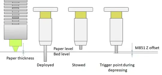
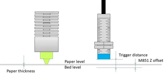
To explicitly answer the raised question, the G29 probes the bed by scanning the surface geometry and the M851 adds an offset for the sensor trigger to the nozzle (at the center). The offset is required to let the firmware know where the nozzle is with respect to the trigger point. The offset therefor lowers the scanned G29 surface, no replacement is taking place. The sketches below illustrate this:


note that the bottom line of the "M851 Z offset" denotes the G29 scanned surface

