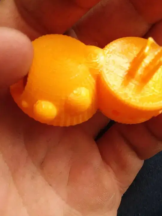
Any deviation from smoothness is caused by irregularity in the material feed, the motion, or both. In this case, I would suggest both.
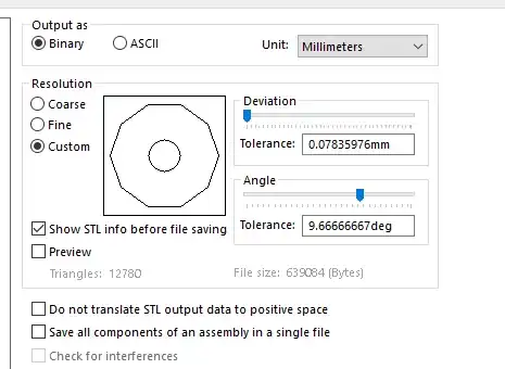
The problem is that current 3D printer control firmware (If someone has a counter-example in the hobbiest space, please add it) prints in linear segments. This starts as @senthil-j-prakash shows in the conversion of the CAD object to an STL file. STL files are made of triangles, which are linear structures. There is no curvature in a triangle, only straight edges and flat faces. Making the triangles as small as possible helps, but it exacerbates the next problem.
The second problem is that each line segment is passed as a separate command to the control firmware. No matter if this is stored on an SD card, or transmitted through USB from the PC to the control firmware, each command defines a short, linear movement. In an ideal world, the printer would precisely reproduce each of this short, linear motions, which would flow smoothly from one to the next.
Unfortunately, the "flowing smoothly" part is difficult to implement, and in some cases isn't actually what you want. If the angle between segments is sharp enough, you don't want to round the corner. When printing approximations to circles, however, one could move continuously, if the commands were sent enough ahead to analyze, and the firmware were clever enough to combine two segments into one smooth, curving motion.
This computation is very difficult to perform on an 8-bit microcontroller, and historically has not been done.
I am using a 32-bit ARM microcontroller and the RepRap firmware, which also does not smoothly merge motion between two low-angle linear motions into one smoother motion.
But, it's not just merging two into one. One must merge a long series of short, linear moves into a long sequence of curved moves. We could be doing motion planning based on splines rather than segments.
But then, we need to cap how much the control processor may change the path because the slicing software needs to predict very closely where each extruded element will lie. Adjacent elements (additional perimeters and infill) must be placed to touch those elements for bonding and strength. if the control processor has moved an element too far, it could either not connect with, or interfere with, an element that is placed later.
But, enough of that rant about the technical difficulties.
For your particular machine, it is likely to be moving in fits and starts because of the short, linear commands. Anything you do that improves the print quality will help with the ribs, and make them look more like facets.
Check the belt tension, the backlash, and the stiffness of the whole machine. Try using slower speed and acceleration settings. If you are printing from a PC through USB or the network, try printing from an SD card. (If printing from an SD card, try printing over USB or the network).
Good luck, and keep printing! Tell others of your experiences.

