12

I would really like to be able to print moving parts that fit well enough to move without excessive friction, but also aren't excessively loose. Using an Ultimaker 2, what should be my expectations be, and how would I go about produce well fitting parts?

Using a tool like Openscad to generate parametric parts is really useful because it facilitates the creation of geometrically precise parts such as cogs and drive shafts, which also have precise dimensions. The problem arises when the parts are printed and joined together.

I recently printed some cogs that were supposed to be able to rotate freely around a shaft, which was also printed. I made the shaft about 0.1 mm smaller than the center hole of the cog expecting it to be able to rotate freely, however I found that I had to bore out the center hole slightly and sand down the shaft. I then found that the boring was imprecise and the center of rotation was off center.
  • Although it is an interesting question it is vague and broad. There are like a dozen of different parameters you should mention. For example what type of motion are you talking about? rotational or linear? what is excessive friction and excessive looseness in your opinion? what material are you using, what is the printing orientation? what are your printing parameters (speed, layer thickness...)? if you really need surface quality then post-processing is unavoidable. you may use acetone smoothing or machining. but as other guys have mentioned try and error is the final solution. – Foad Nov 02 '17 at 15:41
  • Most machine shops work with a +-.005" (.010" total) general tolerance on metal and you gave less than half of that for a 3D print. You will have to experiment with your printer to find what it can do but I don't know of any printer (SLA, FFM, etc) that can hold .004" without some type of post processing on the print. – tjb1 Nov 02 '17 at 18:40

3 Answers3

5

There are a lot of factors to 3D printing parts that work and fit together.

A lot of it will be discovered by trial and error, but let's try to put you on the right path.

First your material is what matters the most. Specifically their coefficient of thermal expansion, i.e. how much can the plastic change when heat is applied. PLA's coefficient is low compared to ABS, for example. Which is why the MakerBot can print without a heated bed, but it cannot print ABS with any success.

Here is a list of coefficient of thermal expansions by material.

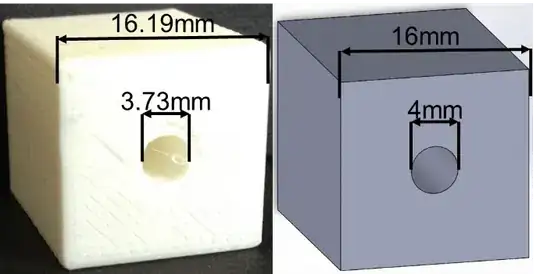
What you want to do next is to print out a few test items and see for yourself. Below is an example of reality vs. expectation. As you can see the circle shrinks. It will never expand. So you will always make it bigger than you need. It is also good to note in this example below that the block itself is Larger than expected. The best solution is to not expect high tolerances and build a lot of flex into your designs.

Example of thermal expansion

Generally you want the hole size larger. If I wanted a 4 mm minimum hole, then I would likely make it 5+ mm.

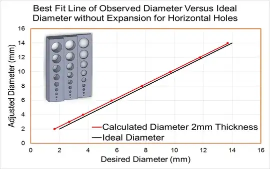
The best thing you can do is print out a tray and document how different the sizes are. Also, do the same with a print of various peg sizes. Below is an example of such a tray.

Example of a print of various holes

Images taken from this link, The Innovation Station - Tips for Designing 3D Printed Parts.

Greenonline
  • 5,831
  • 7
  • 30
  • 60
StarWind0
  • 3,023
  • 3
  • 12
  • 29
3

I think that you've got the right idea in concept, but benchmarking is typically the best way to prove this out.

You should get in the habit of designing with assembly in mind. This means:

  • Hole sizes should be larger than intended and/or shafts should be smaller than intended
  • Scaling does not always solve the issue! Avoid relying on scale tools as it can result in reducing/enlarging features you did not intend to scale
  • My own experience has shown that a clearance of about 0.005" to 0.010" (~125μm to ~250μm) should be enough. However it may be different for your situation with a different printer, filament, climate, etc.
  • Also consider material shrinkage from the printing process!
tbm0115
  • 6,234
  • 2
  • 18
  • 40
1

I can't attest to the empirical data laid out in the first answer, but I've had to deal with a lot of components printed in two parts to be connected via design-incorporated channels. I always found that, as a reference, a box of width and length 0.98" will slide securely, but freely, into a square channel of width and length 1".

Greenonline
  • 5,831
  • 7
  • 30
  • 60
Golightly
  • 136
  • 7
  • 1
    I'll point out I explicitly state they should try themselves as there is no solid answer given the number of factors. Brand to brand of pla will be radically different. Even color to color of the same brand will be different as the pigments change the chemistry. Then we have printers with Fans. Age of materials. The humidity in the air. Ambient temp. There are just too many factors. – StarWind0 Dec 23 '16 at 03:35
  • 2
    I agree completely and don't dispute that individual trial and error will yield your most reliable result. Different geometries and materials all produce different part-to-part characteristics, I just found that the aforementioned box-to-square-channel connection at the stated tolerances have worked pretty well in past. – Golightly Dec 23 '16 at 04:07