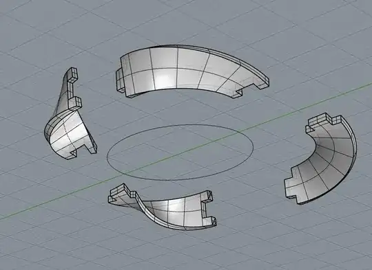
Cutting to pieces
To cut the ring into pieces you can take the intersection() of the object and the quadrant of interest (e.g. using a cube, but a wedge would have worked as well).
/*
 * Möbius Strip
 *
 * r: radius of strip
 * w: width of strip
 * t: thickness of strip
 *
 * The model uses $fs to adjust the smoothness.
 */
module moebius_strip(r = 1, w = 1, t = 1) {
    step = $fs;
    for(azimuth = [0 : step : 360]) {
        x = r * cos(azimuth);
        y = r * sin(azimuth);
        translate([x, y, 0]) {
            rotate([0, azimuth/2, azimuth]) {
                cube([t, step, w], center=true);
            }
        }
    }
}

$fs = 0.5;

xloc=[0,1,-1,-1,1];
yloc=[0,1,1,-1,-1];
//quadrant = 4; // 1, 2, 3 or 4
for(quadrant  = [1 : 1 : 4])
intersection(){
    translate([xloc[quadrant]*10,yloc[quadrant]*10,0]) moebius_strip(r = 30, w = 15, t = 1);
    translate([xloc[quadrant]*10,yloc[quadrant]*10,-(30+15/2)/2]) rotate([0,0,(quadrant-1)*90]) cube(30+15/2);
}
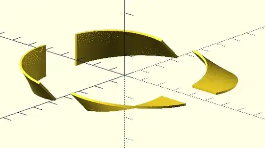
Since tabs and slots are requested, we need to make some adjustments.
Add/subtract tabs to piece
All that is left to do is to cutout a "rectangular" shape at the interfaces. For that we glue or union() a tab on one side and extrude or difference() a tab on the other side, a wedge is used for the intersection() with a smaller sized width Mobius strip.
echo(version=version());
//debug = 0;
//explode = $preview ? 0.1 : 0.0;
//$fn = $preview ? 90 : 360;
//nearly_zero = $preview ? 0.005: 0.0;
tol = 0.01;
/*
 * Möbius Strip
 *
 * r: radius of strip
 * w: width of strip
 * t: thickness of strip
 *
 * The model uses $fs to adjust the smoothness.
 */
module moebius_strip(r = 1, w = 1, t = 1) {
step = $preview ? 2 : 0.5;
    for(azimuth = [0 : step : 360]) {
        x = r * cos(azimuth);
        y = r * sin(azimuth);
        translate([x, y, 0]) {
            rotate([0, azimuth/2, azimuth]) {
                cube([t, step, w], center=true);
            }
        }
    }
}

module wedge(h,r,a)
{
    th=(a%360)/2;
    difference()
    {
        cylinder(h=h,r=r,center=true);
        if(th<90)
        {
            for(n=[-1,1])rotate(-th*n)translate([(r+0.5)*n,0,0])
                cube(size=[r*2+1,r*2+1,h+1],center=true);
        }
        else
        {
            intersection()
            {
                rotate(-th)translate([(r+0.5),(r+0.5),0])
                    cube(size=[r*2+1,r*2+1,h+1],center=true);
                rotate(th)translate([-(r+0.5),(r+0.5),0])
                    cube(size=[r*2+1,r*2+1,h+1],center=true);
            }
        }
    }
}

xloc=[0,1,-1,-1, 1]; // vector indexed by the quadrant, negative value is the negative x-axis
yloc=[0,1, 1,-1,-1]; // vector indexed by the quadrant, negative value is the negative y-axis
offsetVal=0; // can be used to explode the view
quadrant = 1; // 1, 2, 3 or 4 resp. for xy, -xy, -x-y or x-y
//for(quadrant = [1 : 1 : 4]){ // now commented to used single single quadrant
    difference(){ // for extruding the tab
        union(){ // for adding the tab
            intersection(){
                translate([xloc[quadrant]*offsetVal,yloc[quadrant]*offsetVal,0]) moebius_strip(r = 30, w = 15, t = 1); // Mobius belt
                translate([xloc[quadrant]*offsetVal,yloc[quadrant]*offsetVal,-(30+15/2)/2]) rotate([0,0,(quadrant-1)*90]) cube(30+15/2); // quadrant cube
            }
            intersection(){
                moebius_strip(r = 30, w = 7.5, t = 1); // Mobius belt with smaller width
                rotate([0,0,(quadrant-1)*90]){
                   wedge((30+15/2), (30+15/2), 10); // intersect with wedge to get a tab that extends the quadrant piece
                }
            }
        }
        intersection(){
            moebius_strip(r = 30, w = 7.5, t = 1+tol); // Mobius belt with smaller width and increased thickness for better cutting out negative tab
            rotate([0,0,(quadrant-2)*90]){
               wedge((30+15/2), (30+15/2), 10); // intersect with wedge to get a tab that extrudes the quadrant piece
            }
        }
    }
//}
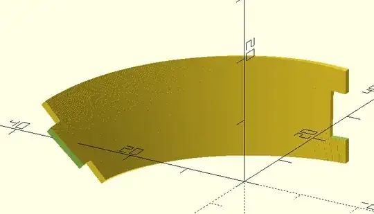
Note that this takes some time to render (F6), the preview (F5) didn't even show because of too much elements. Just change the value of quadrant = 1; to 2, 3 or 4 for the other segments.
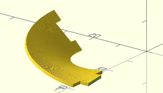
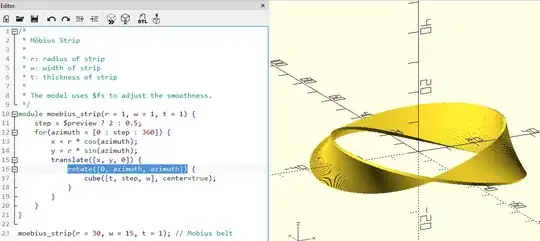
Please note that the image from the question is not what is created with the Mobius script, to generate that object rotate([0, azimuth/2, azimuth]) needs to be changed to rotate([0, azimuth, azimuth])
