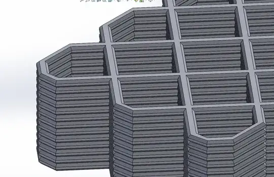
This may sound ridiculous but I'm looking for help regarding turning sliced models such as this...
 ...into something that can be subject to Finite Element Analysis. Note that I'm interested in producing solid models that closely match the geometry of actual printed parts, which themselves can be subject to materials testing with a view to rank infill patterns/parameters, and validate/tune/invalidate the theoretical modelling.
I have not chosen to do this, it is required of me by my university. It seems an absurd thing to ask of an undergraduate with very little experience of either topic but I gotta try. In theory I'm going to need to produce quite a lot of solid models for the FEA so the less time-consuming the better.
Things I have Tried:
Exporting a mesh using the "Export Toolpaths as .OBJ" function of prusa slicer. This produces a zero-volume mesh with lots of self intersecting faces that make it rather unfriendly with software like solidworks and inventor. I opened the .OBJ in meshlab and and after a lot of ill-informed experimentation, had no luck in taming its geometry. I did manage to essentially sketch a silhouette of a .OBJ layer in solidworks and extrude-chamfer-pattern-combine that into something approximating the sliced model but it was laborious.
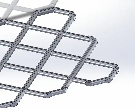
Converting .GCODE toolpaths to .DXF, opening them as a sketch in solidworks and then applying a custom weldment profile to each line. This was easier but doesn't have the properties of a solid body, can't be patterened, and is riddled with discontinuities.


Im currently looking into using Slic3r to export slices as .SVG files which may serves as a basis for extrusions.
Any help or insights into this would be so very much appreciated.