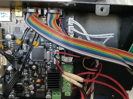
I recently changed the mainboard on my Ender CR-20 Pro because the SD card slot started acting up. I replaced it with the same spare part, hooked everything up (after having a bit of a fight unplugging it from the old mainboard as everything was glued down...), and started the printer. Things looked mostly good, but the heated bed temperature was stuck at 113 °C (even after restarting, flashing the firmware again, or anything else). Just to be clear, it's just the firmware thinking it is 113 °C, it is in fact cool.
My initial thought was that I probably broke the thermistor of the heated bed somehow when installing the new mainboard and was almost buying a new heated bed already. However, I did (luckily) decide to just quickly swap the thermistors, connected the hotend thermistor to the heat bed connectors, and the heated bed thermistor to the hotend connectors. Interestingly the same result, hotend now shows the temperature of the heated bed (put a fan on the thermistor of the heated bed to verify) and the heated bed is still stuck on 113°.
With these results, it seemed obvious that the issue must be with the mainboard (broken connector or line/resistor whatever) and not the thermistor on the heated bed. Since my original issues with the old mainboard were unrelated I figured I'd just throw in the old mainboard and deal with the annoying SD card issue until I get a replaced mainboard through warranty. I removed all the connectors and put them on the old mainboard again. I turned on the printer again and now the heated bed is stuck at 168 °C. This has been working just a couple of hours ago. Same results as with the new main board, when switching hotend and heated bed it shows the right temperature still only on the hotend display.
I am somewhat flabbergasted, there are not that many connectors, and all of them are properly labeled, so I know that I have connected it to the right connector. I know that the connector on the old mainboard is functioning fine.
Does anyone have any idea what could be causing this?
If it helps, here is a picture of the wiring of the relevant parts
