1

I am trying to create a two-piece snap-fit or joint using a 3D printer (Resin). After that, I plan to coat the joint with a conductive spray and create an electrical connection when the two pieces are joined together.

Has this been done before? Are certain types of joint mechanism recommended?

I will probably use carbon spray because it is cheaper than others. However, after the spray dries it can start to flake and thin, so I might need a couple of rounds of coating or something else. Any tips are appreciated.

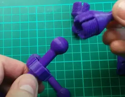
However, more importantly is the joint mechanism - this is what I had in mind:

Plastic ball joint example

The signal would be a DC current only, in the µA range and the targeted resistance would be less than 20 Ω.

Can this work? If not, what are my alternatives?
Greenonline
  • 5,831
  • 7
  • 30
  • 60
Anwer Ak
  • 11
  • 2
  • 4
    Hi and welcome to Stack Exchange. There seem to be two questions here: (1) Which joint mechanism, and; (2) Which (spray-on) coating to use... Generally, it is better to have just one query per post, as it makes the post simpler to answer, rather than having a number of disparate questions in one post. However, in this case, the queries seem to be inter-related. Nevertheless, more details *may* be required (the more info you can provide, the more likely it is that you will get an answer). Also "it starts to bring"... what does that mean? Do you mean "starts to *bind*"? Please [edit] & clarify. – Greenonline Jun 13 '22 at 15:45
  • I would be worried about wear. – R.. GitHub STOP HELPING ICE Jun 13 '22 at 16:31
  • You could use graphite between your conductive layers to reduce wear. – Perry Webb Jun 13 '22 at 17:45
  • You could try experimenting with anti-sieze compound in the joint. It contains a lot of graphite but it's so fine I'm not sure it would conduct very well. But at least it's messy! Another possibility is heat sink compound. Generally, things that are thermally conductive tend to be electrically conductive too. – allardjd Jun 13 '22 at 22:29
  • This can work and with enough practice you will be able to keep the resistance down enough as long as the connection is snug enough, but anything except continuous DC won't survive. More technical: any signals (even if just binary high-low at low frequency) you'd try to communicate over them will have skewed slopes. – Mast Jun 14 '22 at 05:38

2 Answers2

2

Electroforming is the process of applying a conductive paint to a non-conductive surface. Once dry, the object is subjected to a process similar to electroplating, in that molecules of a conductive, more durable metal are bonded to the conductive paint, which is bonded to the 3D printed part.

Typical metals would be nickel, which is quite conductive, as well as copper, known for conductivity. One could be somewhat absurd and perform the same process with silver and gold. The absurdity is related to the expense of those materials.

The link covers using copper, but I believe that nickel would be more durable.

Your joint selection is more related to the strength of the design and contact surface area and may be better suited for a more detailed separate question.

electroformed 3d printed calibration cube As usual, image from linked site.

fred_dot_u
  • 10,532
  • 1
  • 10
  • 24
1

For your task you basically have several options:

  1. Electroforming (see @fred_dot_u answer). Pros: high electrical conductivity due to actual metal layer; very low friction between polished metal layers. Cons: the process is quite dirty and requires additional materials and processing, plus some skill to produce results of appropriate quality.
  2. Conductive filament (e.h. PLA from Makerbot). Pros: direct printing of any form. Cons: high price, probably tricky to print with, high current resistance.
  3. Sliding electrical connections (e.g. as in brushed motors or magnetic USB charging cables). Pros: when properly executed will be very durable and probably could even reuse parts from existing markets (brushed motors use this trick for very long time). Cons: requires additional engineering and redesign of your existing parts.
  4. Wireless connection (e.g. parts use radio/Bluetooth/WiFi for communicating). Pros: independent functionality of each 'limb'. Cons: independent power sources required for each limb; complex communication means.
  5. Optical signalling. Pros: no electrical connections; depending on your use-case might fall in-between wireless connection (without the need of additional power source) and sliding/magnetic connections. Cons: requires skills and tools to work with fiberoptics, which is totally different story.

Depending on your resources, requirements, skills and time you would chose one of above. You may also find some alternative solutions from engineering world.