4

I'm trying to make a frame for a lithograph that I plan to 3D print for my wife for Mother's Day. I typically will have my differences be exactly the right size (rather than oversizing it for the sake of the preview) because it gives me a good feel for how accurate my math is (particularly when I'm accounting for the horizontal margin created by the compressed filament coming out of the nozzle).

In this case, however, it came back to bite me. I debugged this issue for quite a while assuming I had miscalculated something or that I had confused my order of rotations somehow.

Eventually, I oversized my cutout and sure enough, the holes appeared correctly. After poking at it, I realized I only need 0.000005 mm on either side of my cutout for it to render correctly!

I've created a minimal reproducible example of my issue here:

outerRadius = 100;
height = 40;

wallWidth = 2;

innerRadius = outerRadius - wallWidth / sin(60);
apothem = innerRadius * cos(180 / 6);

// change this to 0 and see what happens!!
holeSizeCorrection = 0.00001;

module holes() {
    for (face = [0:5]) {
        rotate([0, 0, face * 60 + 30])
            translate([apothem - holeSizeCorrection / 2, 0, height / 2])
                rotate([0, 90, 0])
                    cylinder(h = wallWidth + holeSizeCorrection, r = height / 4, $fn = 4);
    }    
}

color("orange") difference() {
    $fn = 6;
    
    cylinder(h = height, r = outerRadius);
    
    translate([0, 0, -height/4]) // because if it's exactly right, you can't see inside
        cylinder(h = height * 2, r = innerRadius);

    color("blue") holes();
}

When the holes I'm trying to cut in the polygon are exactly the width of the wall, it renders the preview correctly but the rendered output is incorrect. To verify that the shape was correct, I moved the holes out of the difference and it looks like this: enter image description here
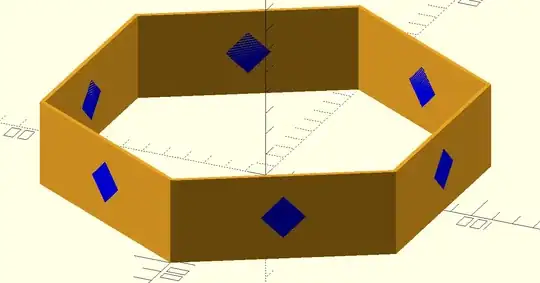
The preview (aside from the strange exact cut issue that usually happens) is correct as well. But, when I render it, it looks like this: enter image description here
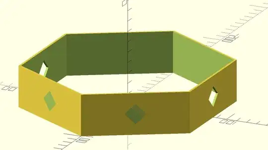
But, if I have the hole shape stick out 0.000005 mm on either side, it renders just fine! enter image description here
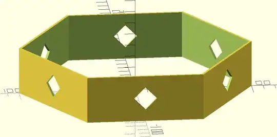
Now that I know to look for this kind of thing, it'll probably save me debugging time in the future. :) But, it would be nice to know if I've done something wrong as well.
D. Patrick
  • 145
  • 5
  • We are not a general 3D design place. What makes this relevant to 3D printing? – Trish Mar 18 '21 at 15:16
  • 1
    @Trish, I plan to 3D print this shape. Also, I assumed there's an `openscad` tag for a reason (for better or worse). I think OpenScad is a relatively popular CAD for folks interested in 3D printing. When I searched for "stackexchange openscad", 3dprinting was the first 3 results. This is all just to answer your question . . . not to argue that it belongs here . . . I think you have a valid meta question for a beta 3d printing stack exchange. My personal belief is that this community will likely end up discussing modeling tools as much as slicing tools (if not more). – D. Patrick Mar 18 '21 at 16:09
  • The tag is there for that reason, but the policy is also, that with questions about 3D design, [you should tell how or why your question relates to 3D printing and is not just a modeling question](https://3dprinting.meta.stackexchange.com/questions/501/cad-questions-review). We had to do that because people started to ask questions without relation to 3D printing and treating us as a general 3D modeling SE. Please [edit] your question to include that it is to be a printed project. – Trish Mar 18 '21 at 16:13
  • 1
    @Trish, I added background information to the question so that it'll be more obvious how my issue (precision in my shapes) is associated to 3d printing (being confident that my calculations are correct with regard to nozzle size). – D. Patrick Mar 18 '21 at 16:50
  • A related question: https://3dprinting.stackexchange.com/questions/9794 – user31389 Jan 10 '22 at 18:20

1 Answers1

3

openSCAD simply allows having surface solutions that result in a wall of 0 thickness. The walls appear to clip in those areas and can at times be seen from both sides, like in your example:

a 0 thickness wall clipping

A 0 thickness wall is also exportable into an STL as a set of triangles spun up by vertices that are in each other's plane but have inverted normal vectors for the two sides - which means that the construct exists for the computer - and I have used this in 3D designs for a hologram-effect, even if it does not result in a physically possible property set.

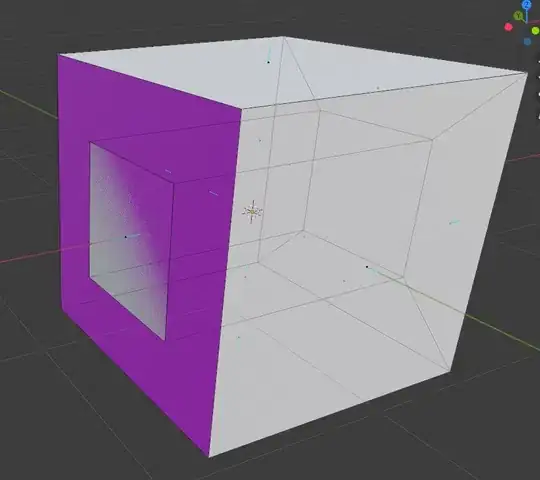
An example of that effect is this cube (made in blender), that has the back wall purple, all others are grey - and the internal wall is at the same X-value as the back wall. You see the grey wall clipping despite the normal of it pointing to +X while the normal of the purple wall is into -X.

enter image description here

By having your cookie-cutter extrude not just to but through the back wall, you force a solution that disallows the 0-surface solution and thus solves the problem of creating those artifact walls.

Note that the 0-surface wall persists in the slicer preview:

enter image description here enter image description here

But rest assured: almost all slicers ignore walls that are too thin to be printed, and a 0 thickness wall especially is ignored:

enter image description here

Trish
  • 20,169
  • 10
  • 43
  • 92