2

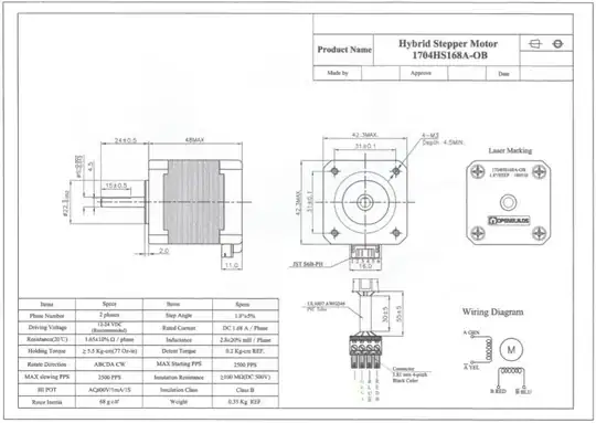
I have been working with the MiniRambo Controller to try to drive 3 stepper motors using the AccelStepper library. The stepper motors are NEMA 17s with the following specifications:

NEMA 17 Stepper Motor Specifications

I am trying to avoid using Marlin Firmware because I want to first make a 2D printer (i.e. a "drawbot") using my own code before upgrading my build to be a 3D printer. Thus far, I have the following for code, where the pin mappings were taken from the Marline firmware and checked against the schematic on the wiki linked above.

#include "AccelStepper.h"
#include "Wire.h"

#define X_STEP_PIN             37
#define X_DIR_PIN              48
#define X_MIN_PIN              12
#define X_MAX_PIN              -1
#define X_ENABLE_PIN           29
#define X_MS1_PIN              40
#define X_MS2_PIN              41

#define Y_STEP_PIN             36
#define Y_DIR_PIN              49
#define Y_MIN_PIN              11
#define Y_MAX_PIN              -1
#define Y_ENABLE_PIN           28
#define Y_MS1_PIN              69
#define Y_MS2_PIN              39

#define Z_STEP_PIN             35
#define Z_DIR_PIN              47
#define Z_MIN_PIN              10
#define Z_MAX_PIN              23
#define Z_ENABLE_PIN           27
#define Z_MS1_PIN              68
#define Z_MS2_PIN              67

#define E0_STEP_PIN            34
#define E0_DIR_PIN             43
#define E0_ENABLE_PIN          26
#define E0_MS1_PIN             65
#define E0_MS2_PIN             66

#define MOTOR_CURRENT_PWM_XY_PIN 46
#define MOTOR_CURRENT_PWM_Z_PIN  45
#define MOTOR_CURRENT_PWM_E_PIN  44
#define LED_PIN             13

#define ELECTRONICS "RAMBo13a"

AccelStepper stepper(1, Y_STEP_PIN, Y_DIR_PIN); // 1 = Driver

void setup() {  

  analogWrite(46,166);

  stepper.setMaxSpeed(200);
  stepper.setSpeed(50);
  stepper.setAcceleration(10);

  stepper.setEnablePin(Y_ENABLE_PIN);
  stepper.setPinsInverted(false, false, true); //invert logic of enable pin
  stepper.enableOutputs();
}

void loop() {
  stepper.runToNewPosition(0);

  stepper.moveTo(500);
  while (stepper.currentPosition() != 300)
    stepper.run();
}

Currently, my motors will move on very rare, seemingly unpredictable occasions. When they do move, they tick once and then stop moving. Since I still see some of this behavior from time-to-time I don't think I have burnt out my drivers - but who knows. The MiniRambo uses four A4982 stepper motor drivers.

I calculated the value to analogWrite to my PWM pin by referencing the Marlin firmware which states the following for the MiniRambo:

#define MOTOR_CURRENT_PWM_XY_PIN 46
#define MOTOR_CURRENT_PWM_Z_PIN  45
#define MOTOR_CURRENT_PWM_E_PIN  44
// Motor current PWM conversion, PWM value = MotorCurrentSetting * 255 / range
#ifndef MOTOR_CURRENT_PWM_RANGE
  #define MOTOR_CURRENT_PWM_RANGE 2000
#endif
#define DEFAULT_PWM_MOTOR_CURRENT  {1300, 1300, 1250}

Another semi-important piece of information is that I am powering the MiniRambo with a 24V/14.6A power supply.

Any help getting my motors to spin would be greatly appreciated! Further, if you know of a way to test my motor driver to see if it burnt out, I would like to hear about it! When explaining, please keep in mind that I am totally new to the space and not very familiar with much of the electronics (more of a software person). Thank you in advance for your help :)
Trish
  • 20,169
  • 10
  • 43
  • 92
peachykeen
  • 121
  • 1
  • You are asking to write the firmware from scratch, don't you? – Trish Nov 10 '19 at 18:44
  • Yup, essentially. I want to write the code that coordinates the movement of the 3 stepper motors (x, y, and z axis) to draw a picture. – peachykeen Nov 10 '19 at 18:46
  • ohhh, a plotter`firmware? https://www.thingiverse.com/search?sort=relevant&q=plotter&type=things&dwh=745dc91b3633ea0 – Trish Nov 11 '19 at 08:26
  • Right, similar to this link. But I would like to build it myself, hence my question. – peachykeen Nov 11 '19 at 13:47
  • 3
    I have frequently gotten the stuttering you describe with a bad connection to the board, usually from poor/dislodged crimping on the wires between the motor to the board. Something to check – K Mmmm Nov 11 '19 at 18:16
  • @KMmmm this was a good thought - I tried attaching the wires/crimps directly to the board rather than going through a plastic connector and the issue persists. – peachykeen Nov 11 '19 at 22:51
  • @peachykeen sometimes cables break in the middle. Try with a short cable, which is fresh, as kind of a "teststand". – Trish Nov 12 '19 at 14:24
  • 1
    There could be a plethora of things you're doing wrong! That's way too much scope for a question like this? Are you sure the driver's aren't shutting down because of over current? Could they be resetting due to brown outs? Are you trying to drive them too fast? Are the motors good? Are the drivers good? Please state/give us answers to how you know everything has been hooked up properly. – user77232 Nov 12 '19 at 14:48
  • 1
    @user77232 I will try to answer your questions as best I can. Too much current? Well I posted my calculation above. Brown-outs? How would I test for this? My PS is brand new and when measured doesn't spike or drop. Driving too fast? I don't think so, I am at the lower end of the speed. Are the drivers good? Well, I just got the controller, but perhaps I could have burnt them out. Hence, my question about testing for a burnt out driver. Hooked up properly? I followed the schematic on the wiki linked above. If you want a screenshot I can provide that too. – peachykeen Nov 12 '19 at 15:04
  • Put 12v light bulbs on the output of the drivers to see if they blink when you give step commands. – user77232 Nov 12 '19 at 15:32
  • @user77232 Would I be able to use a multimeter here? – peachykeen Nov 12 '19 at 17:16
  • @peachykeen, nope. Gotta use an Oscilloscope or a bulb – user77232 Nov 13 '19 at 04:09
  • I solved my issue. I read one of the diagrams wrong and hooked my wires up incorrectly. :( – peachykeen Nov 15 '19 at 20:40

0 Answers0