3

In regards to a part that I'm having printed remotely (by two processes:- stereolithography and laser sintering), I've been advised by the 3d printing company that 'the triangulation of the file is rather rough'.

In this particular instance, it probably doesn't matter, but for the future, are there any tips to improving 'triangulation' when generating forms in AutoCAD?

Note, AutoCAD's FACETRES variable is set to 10.

Strawberry
  • 133
  • 5

3 Answers3

2

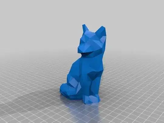
The phrase "triangulation of the file is rather rough" is somewhat vague, but one can interpret it to mean that the surface is what is considered "low poly" in the 3D modeling world.

low poly fox

From Thingiverse, this low poly fox shows an intentionally reduced poly surface. I'm not suggesting that your models appear this distorted, but it may give a hint to what the service is referencing.

Consider to load your model into a program such as Meshmixer, which will show you the triangles in 'W'ireframe mode. If there are few triangles over a surface, you can get the aforementioned effect.

Meshmixer also allows you to increase the mesh count, possibly improving the surface and satisfying the requirements of the printing service.

fred_dot_u
  • 10,532
  • 1
  • 10
  • 24
  • Regarding your last paragraph, that's like when the 2D poster printing shop tells you your 400px jpeg isn't sufficient resolution so you upscale it 10x and send it back to them. If the mesh is insufficient, you have to go back to the original source and produce something better, not "upscale" (add polys to) the bad mesh. – R.. GitHub STOP HELPING ICE Jun 21 '19 at 14:58
2

Most CAD tools generate quite low-res triangulations. The ideal solution is to avoid using the CAD tool to generate them. For example, if the print shop can accept your CAD files directly, they may have other software that can triangulate them. For example, if the shop uses GrabCAD Print to slice your parts, that software can open CAD files directly, and produce much better triangulations than exporting from the CAD software. (In this case they won't be using GCP, which doesn't support the print technologies you mention, but it's just an example: some other vendors' tools have the same functionality.)

If you don't wish to send your original CAD parts, check if your tool can export Parasolid files (.x_t or .x_b). They contain the original boundary representation your CAD tool uses to represent geometry, but not the feature structure, constraints, or design intent.
Dan Hulme
  • 877
  • 1
  • 8
  • 20
0

This thread and this article, both on Autodesks website, suggest altering the FACETRES system variable to 10 to achieve a higher-quality .stl export.

Alternatively, you can use the 3DPRINT command for FACETRES to be increased automatically, which will then offer an .stl export or to send the file directly to a 3D printing service.

towe
  • 1,307
  • 5
  • 9
  • Hi - Thanks - I should have mentioned that facetres was already set to 10. I'll edit accordingly... – Strawberry Jun 21 '19 at 13:39
  • Maybe this applies? https://forums.autodesk.com/t5/autocad-forum/autocad-2018-facetres/m-p/7466483#M902878 Other than that, I would try exporting to a "lossless" format such as .step and exporting the .stl from another software suite like Fusion 360 or FreeCAD. – towe Jun 21 '19 at 13:49