Introduction
-
-
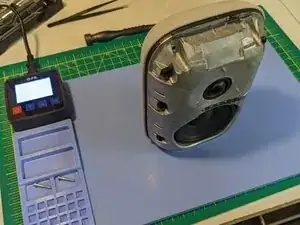
The recycled plastic front cover is press-fit onto the device body and connected by a flex cable that can be easily disconnected by hand.
-
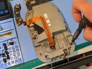
Mounted on the underside of the outer front enclosure are the touch sensors along with a small daughter board affixed by three Torx IP screws.
-
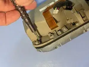
Press a simple pick into the seam between the front and back housing, and pry gently along the seam separating the enclosure covers from the body. If the front cover is difficult to pry off, you might need to insert a flathead screwdriver into the seam and rotate to lift the cover off of the body.
-
Once the front enclosure loosens a little, it should easily start to “pop” off. Once off, carefully flip up the front enclosure to access the flex cable. Disconnect the cable to free the front enclosure.
-
-
-
Fastened to the aluminium body with two T6 screws is the LED light bar.
-
Using tweezers or pliers, gently disconnect the flex cable from the light bar. Be sure to pull on the plastic tab as this cable is very delicate.
-
Using a standard T6 driver, remove the two screws and remove the light board.
-
-
-
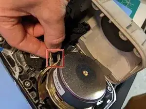
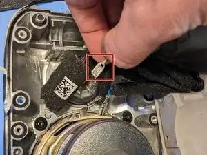
Six rubber receivers are press-fit into the aluminium body. This seat fastens the front enclosure to the body, but it must be removed to access the body screws.
-
With tweezers or pliers, grab onto the rubber and pull. They should pop right out.
-
-
-
There's a recycled plastic and rubber foot affixed to the bottom of the device. This acts as a higher-friction softer foot so as not to scratch surfaces, like wood, and to dampen vibrations. It also covers the re-flash port. This footing is held on by a light seam of adhesive that is easily compromised.
-
Using a controlled heat source, warm the foot to loosen the adhesive.
-
Insert a pick between the foot and device body to pry them apart. If warmed adequately, the foot should be easy to pop off.
-
-
-
With the rubber receivers removed, six T10 screws hold the metal core of the device to the back plastic/fabric enclosure cover.
-
Using a T10 driver, remove the six screws (four were under the rubber receivers + the two screws at the top).
-
-
-
With all six T10 screws unfastened, you can flip off the back cover. The back cover has a small daughterboard for the mute switch connected by a small flex cable. Rotate the cover up towards the top of the device so as not to put any strain on the flex cable.
-
Carefully disconnect the flex cable.
-
-
-
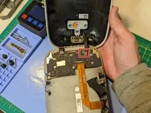
At this point, the inner metal core is still sealed; however, the main logic board (MLB) is visible. Try to avoid removing this. It is not necessary to remove this to open the metal core to access the speaker. We are only removing it here because this is a teardown.
-
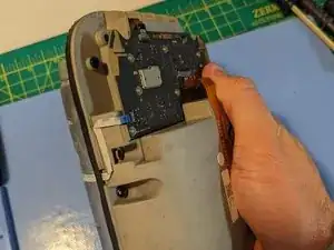
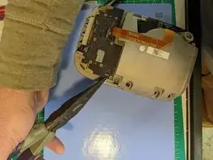
Using your fingers, tweezers or pliers, gently pull on the plastic pull tabs to disconnect the flex cables from the MLB.
-
-
-
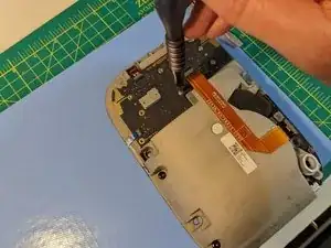
Unfasten the T6 screws that affix the MLB to the metal core and remove the MLB from the metal core body.
-
-
-
There's a separate daughter board that holds the barrel jack power receptacle, distributes power to the MLB and offers a connection terminal for all of the speaker wires.
-
Disconnect the audio cables from the white connector port.
-
Unscrew the five T5 screws.
-
Once the daughter board is free from the metal core, carefully disconnect the main power flex cable that travels to the MLB.
-
-
-
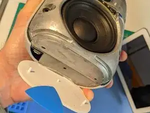
The body is formed by a recycled aluminium half and a recycled magnesium half in a clamshell fashion.
-
Unfasten the six T10 screws that hold the metal core together.
-
-
-
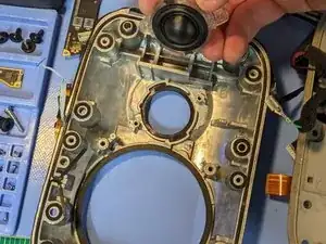
Using a flathead screwdriver, simply insert it into the seam between the two halves and rotate to separate the two metal halves.
-
-
-
Without straining the cables, reach into the core to remove the four spade electrical wire connectors. (I was able to do this without a tool.)
-
-
-
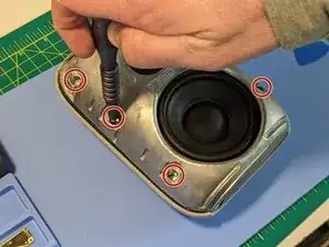
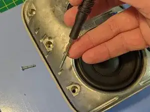
Using a T6 driver, remove the four screws on each speaker. Be aware, that the large speaker is heavy and very magnetic.
-
Lift the speakers out of the housing.
-


5 comments
Pretty cool! Looks like a well-built product. Very good job on your part disassembling.
ceekay_ -
Hi Do you have any information about the WiFi part in this product?
Who is the supplier inside it?
Thank you.
KJcolin -
The sound was very good for me. Now I also see it looks like an excellently designed product. Should be reliable.
Thank you BoulderMaker!
Leonid -