Introduction
-
-
It is much easier to insert and remove the muff body clips by rotating them 90°. The plastic stud underneath is oval in shape and is indicated in green on the image.
-
Remove the pad by inserting a large flathead screwdriver or butter knife just underneath the plastic backing plate of the padding and continuing all the way through to the muff shell. Then twist forcefully, and the underlying plastic should pop off. Using a finger is nearly impossible on the first attempt, but works on subsequent attempts.
-
Now it's free! But be careful to not twist or yank the cable.
-
-
-
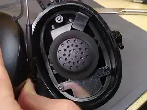
Front view of the right earcup
-
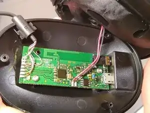
The backside view of the earcup shows the circuit board. There is a cavity on the ear cup, but it looks to only be as deep as necessary. Wires going to the speaker are strain relieved with glue (not pictured)
-
Another view shows the BES2000 SoC
-
-
-
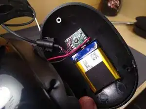
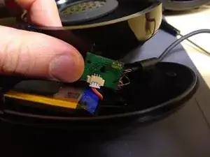
Contains a battery and connector PCB. Battery type is 603040 lithium ion, dimensions are 6mm thick X 30mm tall X 42mm wide, with a 3-pin JST (includes thermistor apparently)
-
-
-
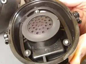
The left side speaker and its cavity are 37mm wide and 16mm deep. There is extra space underneath the speaker, maybe for better acoustics. The rubber gasket is glued on. The right side had a similar cavity, although not as deep.
-
13 comments
How about the headband? Is it replaceable? Or maybe the ear cup tip?
RobCow -
I don't know if you can find the headband as a replacement part. However, the gel ear cups are replaceable. Just look for 3M Peltor Gel Ear Cup replacements.
Replacement gel cushions for PELTOR style headphones such as the Optim 105 do not work. The size is different. There are 3M WorkTunes specific replacement gel cushions available from 3M (part no. GEL-HYG). I purchased two spare sets of genuine 3M WorkTunes replacement gel cushions on Amazon back in March 2022 when they were clearing them out for USD$12.73/each. Since I already had a pair of Optim 105's, I thought I might see how they work with them and perhaps get a set for them too (I have two pair of WorkTunes hence a set of spares for each). Found out they do not fit the Optim 105's and the product description on Amazon shows what models are compatible.
robert -
Thanks Robert. I forget where I read that.
could someone tell me where i could find the wire that connects the two shells together. I know the wire has 6 conductors and its outside diameter is 2.6mm or .102''. mine is broke. thank you.
I don't know of an exact replacement, 3M doesn't look to list anything. Part of the difficulty of replacing it is that the rubbery "block" that holds the cable in is injected molded around the cable. But if you're willing to MacGyver, hot glue and some 6-conductor cable from Amazon (fast shipping, but kinda thick 28awg https://www.amazon.com/Striveday-conduct...) or AliExpress (30awg, but takes a month to arrive, https://www.aliexpress.com/item/22558003...) should work fine. Going the MacGyver route, I don't think the thickness will matter that much. Good luck!
Can someone tell me the order or the 6 wires in right side circuit board from top to bottom can’t tell in pic thankyou


