Introduction

Follow the steps in this guide to replace the Wi-Fi/Bluetooth antenna in an iPhone 6s Plus.

  1. Qcih26YoP1i6OFGn
    • Optionally, apply mild heat to the lower edge of the iPhone using an iOpener or hair dryer for about a minute.

    • Heat softens the adhesive securing the display, making it easier to open.

  2. uBB2k6Qa5kBiKVq1
    • Opening the display on the 6s Plus separates a thin strip of adhesive around the perimeter of the display. If you prefer to replace the adhesive, have a set of new adhesive strips ready before you continue. It's possible to complete the repair without replacing the adhesive, and you probably won't notice any difference in functionality.

    • Apply a suction cup to the lower left corner of the display assembly.

    • If your display is badly cracked, covering it with a layer of clear packing tape may allow the suction cup to adhere. Alternatively, very strong tape may be used instead of the suction cup. If all else fails, you can superglue the suction cup to the broken screen.

  3. MxJDUG1SaPyedRhM
    MxJDUG1SaPyedRhM
    ZZRaVnOy2TupljD1
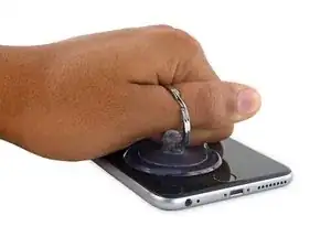
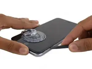
    • Pull up on the suction cup with firm, constant pressure to create a slight gap between the front panel and rear case.

    • Pulling too hard may damage the display assembly. Apply just enough pressure to create a small gap between the display assembly and the rear case.

  4. ACUqUJ4LgUaMa41t
    ACUqUJ4LgUaMa41t
    wZ5e3bm23FflqVB3
    tAAPqg3h36SZ6CEc
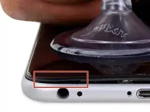
    • The safest place to pry from is the notch in the front panel above the headphone jack.

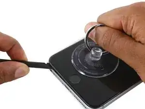
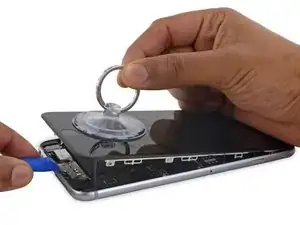
    • While still maintaining pressure on the suction cup, insert the flat tip of a spudger into the gap, directly above the headphone jack.

  5. bH5ErqeUBGDUaVDR
    bH5ErqeUBGDUaVDR
    omF3krqUHgLoDYQv
    • Twist the spudger to widen the gap between the front panel and the rear case.

  6. mlSHxHqFwjZGSB12
    mlSHxHqFwjZGSB12
    oFoQSjDJmLDLUHXs
    GKb1nKlMXR56aoPF
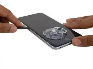
    • While firmly pulling up on the suction cup, slide the edge of the spudger under the bottom left corner of the display.

  7. dQIRABOiS5BZVBYt
    dQIRABOiS5BZVBYt
    h41s3GchCn25kqwG
    • Slide the tip of the spudger up the left side of the phone, between the front panel and the rear case.

  8. EXwLBVBVdQLaeinc
    EXwLBVBVdQLaeinc
    qOycE1efKPm21oTH
    • Insert the flat tip of the spudger under the right edge of the display.

    • Slide the spudger up the right side.

  9. qM1YCbGYBDwHhNvC
    qM1YCbGYBDwHhNvC
    L1ZdSMZRAPfEh2xc
    • Use a plastic opening tool to hold down the rear case while pulling up the suction cup to open the phone.

    • Do not remove the display completely, or you will damage the data cables connecting the display near the top edge of the iPhone.

  10. wfnZE2aODyIJeyNf
    wfnZE2aODyIJeyNf
    AAXGb4lqONlSQNbS
    • Pull up on the small nub on the suction cup to remove it from the display.

  11. J2Dbr1DPL6tDfW2K
    J2Dbr1DPL6tDfW2K
    xZUQGGfkCaxSyYZY
    XkCUCRTMHrRk5Fph
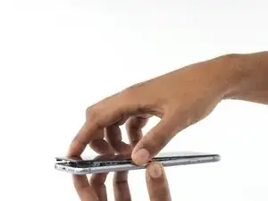
    • Gently grasp the display assembly and lift it up to open the phone, using the clips at the top of the front panel as a hinge.

    • Open the display to about a 90º angle, and lean it against something to keep it propped up while you're working on the phone.

    • Don't open the display more than 90º—it is still connected to the top of the phone by the display, digitizer, and front camera cables which can tear easily.

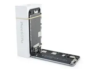
    • Add a rubber band to keep the display securely in place while you work. This prevents undue strain on the display cables.

    • In a pinch, you can use an unopened canned beverage to support the display.

  12. EoflLLcAt1HIbUmO
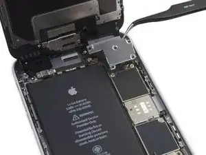
    • Remove two Phillips screws securing the battery connector bracket to the logic board, of the following lengths:

    • One 2.9 mm screw

    • One 2.3 mm screw

    • Throughout this guide, keep careful track of your screws so that each one goes back where it came from during reassembly. Installing a screw in the wrong place can cause permanent damage.

  13. ygoiVVGeB6ZkANKe
    ygoiVVGeB6ZkANKe
    5UTSQPPjPBMuodJe
    • Remove the battery connector bracket.

  14. KOGrCVgncc3ZgZHs
    KOGrCVgncc3ZgZHs
    2YYvqTqfgygsmFlD
    Qm4M5IrUItfwAfGC
    • Use a spudger or a clean fingernail to disconnect the battery connector by prying it straight up off the logic board.

  15. Is3nIUrhLItwpK1y
    Is3nIUrhLItwpK1y
    SAe34wxrJZPMo1qM
    lOrncqNEdhwTPNUX
    • Bend the connector back to ensure it doesn't make contact and power the iPhone on while you're working on it.

  16. 4Tc24beHZNDORBaq
    • Remove the following Phillips screws:

    • Three 1.3 mm screws

    • One 1.6 mm screw

    • One 3.0 mm screw

    • During reassembly, it's critical to place this 3.0 mm screw in the top-right corner of the bracket. Placing it anywhere else may damage the logic board.

  17. O1KQHQPAOgWLK2WE
    O1KQHQPAOgWLK2WE
    KhuAF4InHCFICGGT
    • Remove the display cable bracket.

  18. HS6QAABODK5v43Xa
    HS6QAABODK5v43Xa
    LBajYuVOp4Kwa4hv
    • Be careful to only pry up on the connector itself and not the socket on the logic board.

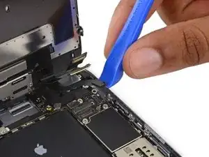
    • Use a plastic opening tool to disconnect the front-facing camera and sensor cable connector.

  19. BYxkF6BrIlXLsDyx
    BYxkF6BrIlXLsDyx
    kttpwbgLMfcYmdht
    • Use a plastic opening tool to disconnect the digitizer cable by prying it straight up from its socket on the logic board.

    • When reconnecting the digitizer cable, do not press the center of the connector. Press one end of the connector, then press the opposite end. Pressing in the center of the connector can bend the component and cause digitizer damage.

  20. FUF4X3u4sIr6DFkV
    FUF4X3u4sIr6DFkV
    jJvlZ4XDy5IGCJsG
    • Make sure the battery is disconnected before you disconnect or reconnect the cable in this step.

    • Disconnect the home button/fingerprint sensor cable by prying it straight up from its socket on the logic board.

  21. mTR16W6Y6SJbIjlY
    mTR16W6Y6SJbIjlY
    Wt6QauSZDsqEhwwk
  22. aYux1TYt6BBEkQSD
    aYux1TYt6BBEkQSD
    ncmFDcUJBTFil6Sd
    PNuWUZKnucS1au2n
    • Peel up any tape covering the iSight camera bracket screws.

  23. YxYgQnCysDGWAcGH
    • Remove the following Phillips screws over the camera bracket:

    • One 1.9 mm screw

    • One 2.4 mm screw

  24. vyGsNM2Sh3UFdTlJ
    vyGsNM2Sh3UFdTlJ
    VQ6CAxaMZPcvAtl5
    • Remove the iSight camera bracket.

  25. Vhk21O3WC1lBdFPp
    Vhk21O3WC1lBdFPp
    VeooO2xafOuPAfZF
    • Disconnect the iSight camera connector from its socket on the logic board.

    • Be sure to pry up only the connector and not the socket on the logic board.

  26. kL1gx6BjURBAHace
    kL1gx6BjURBAHace
    v4CcNFkAgSDQ1quJ
    • Insert the flat end of the spudger between the iSight camera and rear casing.

    • Gently pry the camera out from its housing.

  27. gX4mEaG5sVKPeMgX
    gX4mEaG5sVKPeMgX
    CfVHlRbNWMOdefNJ
    • Remove the iSight camera.

  28. GGcHcOQsKQsa1KMZ
    GGcHcOQsKQsa1KMZ
    AnlFKYRBjsbpTCEI
    • Insert a SIM eject tool into the hole in the SIM tray.

    • Press to eject the SIM tray.

  29. w6ZwfRdVjSEHSLVM
    • Remove the SIM tray.

    • When reinserting the SIM tray, be sure to orient the tray such that the SIM eject hole is on the bottom.

  30. jCxmkO2mgLAdPmJ6
    • Remove the single 1.4 mm Phillips screw holding the NFC bracket in place.

  31. sBVAWWwpQ5ALSQZH
    sBVAWWwpQ5ALSQZH
    LYAup2Vgx6fJhmST
    • Remove the NFC bracket.

  32. 3MJGRPxRPFTjECwF
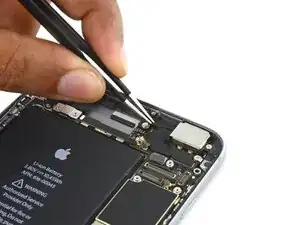
    • Remove the two 2.7 mm Phillips screws securing the audio control cable bracket to the logic board.

  33. rjWrslKYqnP1OHJT
    rjWrslKYqnP1OHJT
    uZ6WZOqIGvumfb3Y
    • Remove the audio control cable bracket.

  34. EcMjmJtP2KDbPrFe
    EcMjmJtP2KDbPrFe
    sALREUVHVSRM2AOT
    • Disconnect the audio control cable by prying its connector straight up from its socket on the logic board.

  35. Z3lDBrZA2aPVTRXs
    Z3lDBrZA2aPVTRXs
    xqCPgUTKvCs6Q3BA
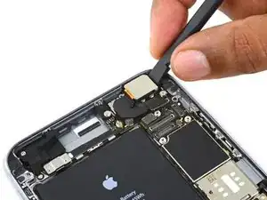
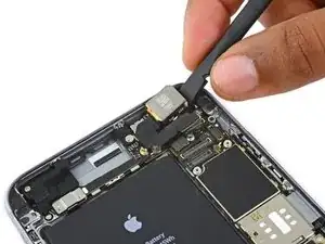
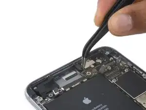
    • Disconnect the cellular antenna cable by prying its connector straight up from its respective socket on the logic board.

  36. WLaZMufBTlmYNnBR
    WLaZMufBTlmYNnBR
    rDG3UBTXmt3vqHJY
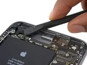
    • Disconnect the Wi-Fi diversity antenna cable by prying its connector up from the logic board.

  37. oHWR4URSoeSXriE6
    oHWR4URSoeSXriE6
    pTkTFaoVvS3iMpHM
    • Disconnect the power button flex cable from its socket on the logic board.

  38. xBswBec22EbYNCO4
    xBswBec22EbYNCO4
    Fo2bGpSJOmMFWwFC
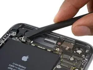
    • Disconnect the Lightning connector interconnect antenna cable by prying it up from the logic board.

  39. 6SYjRZjk5oHKN1q2
    6SYjRZjk5oHKN1q2
    iyKWOcWjSbJfSvgg
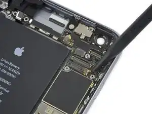
    • Use the flat end of a spudger to disconnect the Lightning connector flex cable from the logic board.

  40. r5u4kFoiwltJ4Bwg
    r5u4kFoiwltJ4Bwg
    dJpMc5M1U2jXisEU
    QplpMKeGnDJ4as3T
    • Deroute the antenna cable from the two clips on the right edge of the logic board.

  41. dmLYxgeKclHMLXAK
    dmLYxgeKclHMLXAK
    OwoxlmhhHODMoBVs
    • Remove the following screws:

    • One 1.3 mm Phillips screw

    • One 2.6 mm Phillips screw

    • One 2.2 mm standoff screw

    • Standoff screws are best removed using a standoff screwdriver or bit.

    • In a pinch, a small flathead screwdriver will do the job—but use extra caution to ensure it doesn't slip and damage surrounding components.

  42. qMCEEZOFSlKP4lWC
    qMCEEZOFSlKP4lWC
    6YFQhEfwZWM2BFKo
    • Remove the bracket.

  43. 3Y2MywBvB5XN1Xxa
    3Y2MywBvB5XN1Xxa
    UmDFtj1OR1BLXyM1
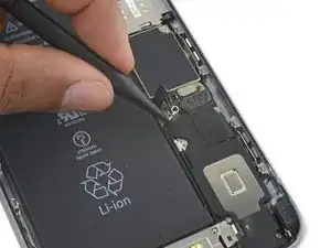
    • Deroute the upper left cellular antenna cable from the first logic board clip by nudging it out from under the clip, towards the battery.

  44. TqGG4JEnIH1dHgUA
    TqGG4JEnIH1dHgUA
    VlsUPmMM3U6jCAgN
    Of25XHgbKGJEUKSw
    • Continue derouting the cellular antenna cable from the second and third logic board clips.

    • Use the pointed tip of a spudger to gently pry the cellular antenna cable from the middle logic board clip.

    • Don't try to remove it by pulling on the cable, as it will tear easily.

    • In order for the cable to reach its socket on the logic board, you must route it above the logic board and underneath the audio control flex cable, as shown in the first photo.

  45. Dcx2hOLrOGnZHRmH
    • Remove the final 2.0 mm Phillips screw directly below the SIM card reader.

  46. Vm5XpRoSAwqLgaan
    Vm5XpRoSAwqLgaan
    on5hRH1RUTwEH3Um
    a1T3WED5AmGMCSIO
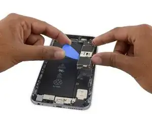
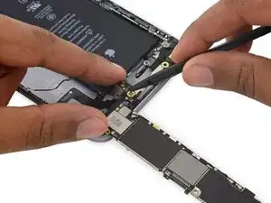
    • Carefully raise—but do not remove—the logic board, lifting it from the bottom edge nearest the Lightning connector.

  47. vkoJ1hoKGZBCWiLa
    vkoJ1hoKGZBCWiLa
    HaySB42xjNIdrVJP
    UtPs2lJba3YyaWPI
    • Tip the logic board up to a vertical position to expose the single antenna connector on the underside, near the top edge of the board.

    • Do not attempt to fully remove the logic board yet, as the Wi-Fi/Bluetooth antenna is still connected to the underside of the board.

  48. 22eUFMZrTdGpiwTf
    22eUFMZrTdGpiwTf
    5OkhkejWbvjqEVwc
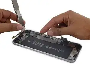
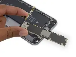
    • Gently lay the logic board upside-down, with the top portion resting against the rear case of the iPhone.

    • Use the flat end of the spudger to disconnect the Wi-Fi/Bluetooth antenna cable from its socket on the back of the logic board.

  49. AqZXGYtPlmvm1Bkb
    • Remove the logic board.

  50. CJF5w5wsXfd3gdLV
    CJF5w5wsXfd3gdLV
    aWkvUFnMPkAJXAoy
    • Remove the sticker over the third screw holding the cellular antenna in place.

  51. xWEeufMGirPPPPE3
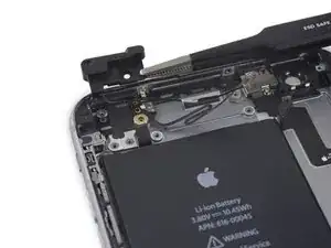
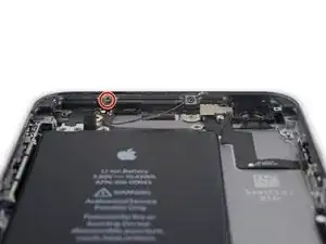
    • Remove the following three Phillips screws holding the cellular antenna in place:

    • One 2.7 mm screw

    • One 1.7 mm screw

    • One 1.3 mm screw

  52. ucdDG35OVQ1aTBwL
    ucdDG35OVQ1aTBwL
    QOTGaBuL1QFUq6dH
    • Remove the cellular antenna.

    Ist it really cellular ?

    Or other function

    Doc Ossi -

  53. 1BOMiPUXpNJPIK2Z
    • Remove the single 1.3 mm Phillips screw securing the antenna to the rear case.

  54. P1WiQ6XC4QqJ31Ri
    P1WiQ6XC4QqJ31Ri
    rPom4whTspTLI5Zj
    • Remove the Wi-Fi/Bluetooth antenna.

Conclusion

To reassemble your device, follow these instructions in reverse order.

Evan Noronha

Member since: 06/02/15

217861 Reputation

15 comments

Omg

That was an intense read.

tedcmacdonald -

in iphone 6s 4.7" wifi antenna is the same and is in the same place?

Łukasz Gałęzewski -

Didn't you forget to mention first step to remove the two little screws by the power connector? First time doing this and I ended up breaking the metal threaded tabs that the screws go into :(

I guess I should have realized it would have screws somewhere and also researched some more before attempting the repair.

Oh well, looks like I will need to get some teflon tape or something to hold things together.

Patrick G -

Exactly! I also broke them, but fortunately I was also replacing the LCD Screen/Digitizer.

edgarjmiranda -

Hi, is this repair guide (and the antenna you sell) also valid for the non functioning bluetooth of an Iphone 6S ?

Basile Clot -

is the antenna function for wifi and bluetooth?

Bench Duarte Jr. -

I recently replaced the loud speaker on a iphone 6s plus which involves all the steps above. Once I put it back together the wifi and bluetooth only worked intementantly and was weak. I took phone back apart and checked all connections and couldn’t see anything wrong. I started putting things back together and was able to get it working again. Now it’s been a few weeks and its back to dropping signal again. My thought is I may have damaged wifi/bluetooth cable, but I also notice several other “wifi” cables and I’m not sure where to begin. I assume since this is the only one that is also associated with bluetooth that this would be it. Am I thinking correctly? Everything else including cellular is functioning properly.

Jason -

Did you ever find a solution to this issue? I recently changed the housing on my iPhone and am having the same issue you describe… Have already replaced the wifi/bluetooth antenna but the problem persists… strange…

Patrick -

Jason,

I replaced the lightning port in my phone and destroyed the bluetooth/wifi antenna in the process. Not having a bluetooth/wifi antenna replacement in my possession, I reassembled the phone and found that my GPS and bluetooth weren’t working. Bought a bluetooth/wifi antenna and installed it a couple days later and my bluetooth and GPS started working again.

The bluetooth/wifi antenna cable is really fragile. Are you sure you didn’t damage the new one when you installed it?

NorthernBigDummy -

congratulations for your time and effort

rose akorfa -

Ip 6 plus can share use with 6s plus?

xiaoochuchu -

My iPhone6s Bluetooth option In the circle, after following this step, can I solve my problem?

jianjam -

Ich frage mich wo das https://www.ebay.de/itm/123934065844 hinkommt ?

atilaibrahim@hotmail.de

Mystery Shopper -

The detailed pictures in this guide are awesome comments also helpful, haven’t done it yet but definitely referring to this when I do! I love this website wish I would’ve known about it before messing up those iPhone some odd years ago lol

Zoraida Martinez -

Clear and professional

Mehrdad.kaveh -