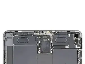
Introduction
This is a prerequisite-only guide! This guide is part of another procedure and is not meant to be used alone.
-
-
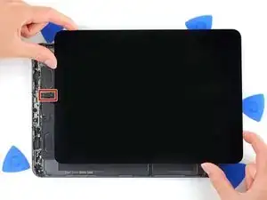
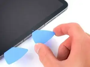
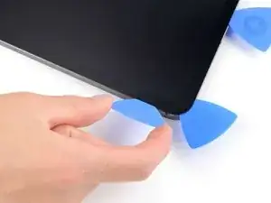
Apply a suction handle to the right edge of the display, about 50 mm from the bottom edge.
-
Pull up on the suction handle with firm, constant pressure to create a gap just small enough to insert an opening pick.
-
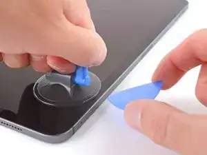
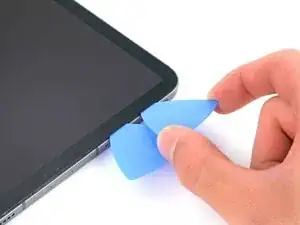
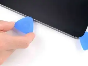
Insert the tip of an opening pick into the gap.
-
-
-
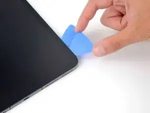
Insert a new opening pick in the gap you just created.
-
Slice the right adhesive, stopping at the top right corner.
-
Leave the pick in the top right corner to prevent the adhesive from re-sealing.
-
-
-
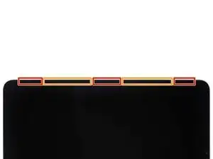
Don't insert an opening pick more than 5 mm near the top left and right edges or you'll damage the ambient light sensors.
-
Don't insert an opening pick more than 1 mm near the middle of the top edge or you'll damage the camera module.
-
-
-
Insert a new opening pick in the gap you just created.
-
Slice the top right adhesive, stopping when you reach the right ambient light sensor.
-
Leave the pick to the right of the sensor to prevent the adhesive from re-sealing.
-
-
-
Insert a new opening pick to the right of the ambient light sensor.
-
Slice the middle section of the top adhesive, stopping when you reach the left ambient light sensor.
-
Leave the pick in to prevent the adhesive from re-sealing.
-
-
-
Insert a new opening pick to the left of the ambient light sensor.
-
Slice the top left adhesive, stopping when you reach the left corner.
-
Once the top adhesive has been sliced, you can remove the two picks near the ambient light sensors.
-
-
-
Insert a new opening pick in the bottom right corner below the existing pick.
-
Slice the bottom right corner adhesive.
-
-
-
Slice the bottom adhesive, stopping at the USB-C port.
-
Leave the pick in to prevent the bottom adhesive from re-sealing.
-
-
-
Slice the remaining bottom adhesive, stopping at the left corner.
-
Leave the pick in the bottom left corner to prevent the bottom adhesive from re-sealing.
-
-
-
The display cables are located within small indents of the frame and require an opening pick to be inserted at a 45° angle.
-
There are flat sections of the frame which require an opening pick to be inserted horizontally.
-
-
-
Insert an opening pick at a 45˚ angle just above the bottom left corner.
-
Carefully slice the left edge, stopping when you reach the flat section of the chassis.
-
-
-
Lower the opening pick so it is horizontal to the display.
-
Continue slicing the left edge until you reach the next indented section of the frame.
-
-
-
Slice the remaining adhesive, making sure to follow the instructions exactly as written.
-
Slice at a 45˚ downward angle and don't insert the pick more than 5 mm.
-
Slice horizontally and don't insert the pick more than 5 mm.
-
-
-
Grab two opposing corners of the display and gently separate the rest of the adhesive.
-
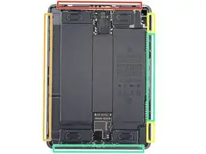
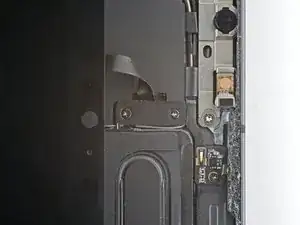
Shift the display towards the bottom right corner of the frame until the ambient light sensor ribbon cable near the top edge is uncovered.
-
-
-
Use a Phillips PH00 screwdriver to remove the two screws securing the ambient light sensor cable bracket to the logic board:
-
One 1.3 mm screw
-
One 2.0 mm screw
-
-
-
Grip the right edge of the display and fold it open like a book.
-
Lay the display down over the left edge of the iPad.
-


To reassemble your device, follow these instructions in reverse order.
