Introduction
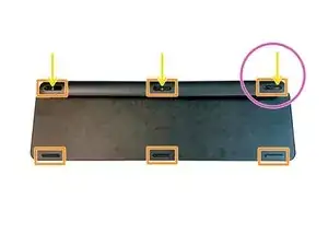
1.Remove the rubber gliders on the backside:
The three gliders on the top are necessary in this step but you will remove the bottom three later anyway so best to do all six at the same time
2.Unscrew the three screws behind the top rubber gliders:
In my case the glue\adhesive covered them
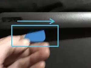
3.Use the ifixit toolkit / picks to open the cover
4.Remove the battery:
Unplug and remove It’s lightly glued on the backside
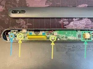
5.Unscrew the little black screw on the PCB which clamps the antenna cable
6.Unscrew the PCB:
Three kind of big silver head screws
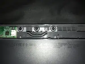
7.Remove the PCB
8.Unplug data cable:
Lift the adhesive tape, then the white part / connector pulls up to release the cable
9.Remove all silver and black screws
10.The backplate cover:
start in the left top and lift / pull very slowly until you completely remove it. It’s pretty robust but the adhesive is very strong so take your time on this step
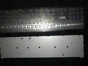
11.Unscrew all the little black screws and the remove the metal base plate
I have uploaded pictures so please take a look at them if needed
Hope this helps and thanks to @Inchness for the help with this guide
-
-
Remove the rubber-feet from the underside
-
Unscrew the three screws behind the top rubber feet
-
Note the leftmost screw is offset to the right, and not in the center
-
Use a plastic opener to remove the cover
-
-
-
Remove the battery
-
Unscrew the little black screw on the PCB witch clamps the antenna cable
-
Unscrew two (slightly larger, silver) phillips screws that secure the PCB
-
Remove PCB
-
Remove the tape securing the serial cable (put it to one side, you'll need to put it back if reassembling)
-


To reassemble your device, follow these instructions in reverse order.

One comment
Do you know how I can turn the keyboard backlight so it stays on, even if if t runs down the battery faster.
I really need that back light. I am willing to risk breaking my keyboard for the reward of having the light. If I am really lucky changing the circuit to add a manual switch for that dang back light :)
I have basic skills and I am still learning...
Thank to all the Content Makers and Fix-It guide makers...!
perhaps I could find the correct voltage for the light and prob with a test light to find the circuit for the back light with out damaging something important, like the old days_?
nazo -