Introduction
This repair guide was authored by the iFixit staff and hasn’t been endorsed by Google. Learn more about our repair guides here.
Use this guide to replace the front camera is your Google Pixel 6a.
For your safety, discharge the battery below 25% before disassembling your phone. This reduces the risk of fire if the battery is accidentally damaged during the repair. If your battery is swollen, take appropriate precautions.
Note: this guide was made using the Verizon GB62Z model, which features a 5G mmWave antenna. Ignore the steps that include the 5G mmWave antenna if you have a different model, as the procedure is identical.
You'll need replacement adhesive in order to complete this repair.
-
-
Insert a SIM eject tool, bit, or straightened paper clip into the SIM card tray hole.
-
Press the SIM eject tool into the SIM card tray hole to eject the SIM card tray.
-
Remove the SIM card tray.
-
-
-
Screen seam: This seam separates the screen from the rest of the phone. Do not pry at this seam.
-
Bezel seam: This is where the plastic bezel designed to protect the screen meets the frame. It's held in place by plastic clips. This is where you should pry.
-
-
-
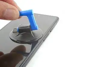
Apply a suction cup to the screen, as close to the center of the right edge as possible.
-
Pull up on the suction cup with strong, steady force to create a gap between the bezel and the frame.
-
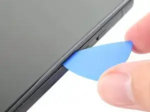
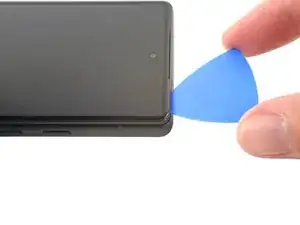
Insert an opening pick into the gap.
-
-
-
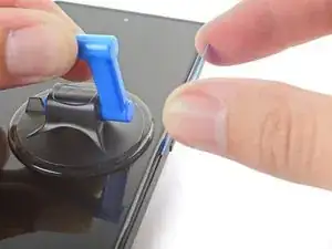
While still applying suction, pivot the pick upwards to a steep angle.
-
Carefully push the pick in while prying to reposition the opening pick into the bezel seam.
-
-
-
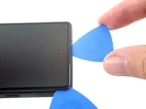
Slide the pick along the right edge to release the plastic clips securing the bezel to the frame.
-
Position the pick at the top-right edge before moving to the next step.
-
-
-
Rotate the opening pick around the top-right corner of the phone to release the clips.
-
Leave the opening pick in the top-right corner to prevent the clips from re-locking.
-
-
-
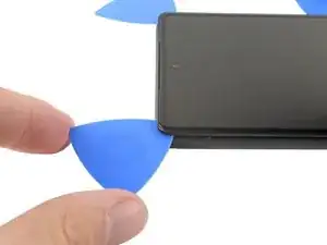
Insert a new opening pick into the gap you just created.
-
Slide the pick along the top edge to release the clips.
-
-
-
Rotate the opening pick around the top-left corner of the phone to release the clips.
-
Leave the opening pick in the top-left corner to prevent the clips from re-locking.
-
-
-
Insert a new opening pick into the gap you just created.
-
Slide the pick along the left edge to release the clips.
-
Repeat the rotating and sliding procedure for the remaining edge.
-
-
-
Lift the right edge of the screen up and towards the left side of the device, like opening a book.
-
Rest the screen upside down and parallel to the frame before continuing.
-
-
-
Use tweezers to bend the left side of the bracket upwards, releasing the metal clip.
-
Remove the display cable bracket.
-
-
-
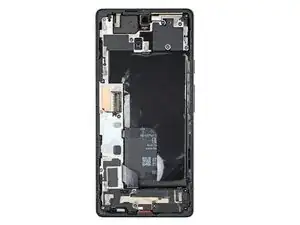
Use a T3 Torx screwdriver to remove the 16 screws securing the midframe to the frame:
-
Nine 4.3 mm screws
-
Four 2.9 mm screws
-
Two 4.9 mm screws
-
One 4.6 mm screw
-
-
-
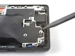
Insert a spudger between the top of the midframe and the frame, near the front camera.
-
Pry up with the spudger to release the top of the midframe from its clips.
-
-
-
Insert a spudger between the bottom left of the midframe and the frame.
-
Pry up with the spudger to release the bottom of the midframe from its clips.
-
-
-
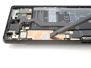
Use the flat end of a spudger to scrape off the thermal paste.
-
Clean any remaining thermal paste with isopropyl alcohol and either a coffee filter or a lint-free cloth.
-
Repeat the cleaning process for the thermal paste on the midframe.
-
-
-
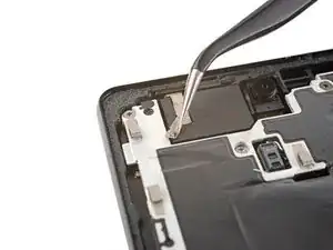
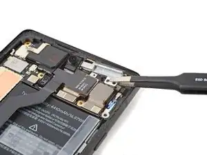
Use a T3 Torx screwdriver to remove the 2.9 mm screw securing the 5G mmWave antenna bracket.
-
-
-
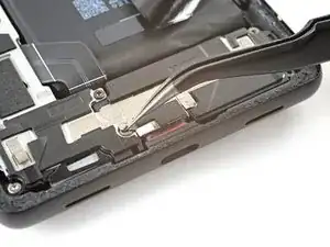
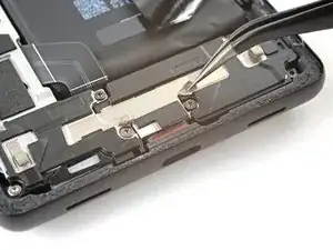
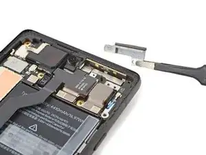
Use tweezers, or your fingers, to pull the bracket towards the right edge of the phone and disconnect its clip.
-
Remove the 5G mmWave antenna bracket.
-
-
-
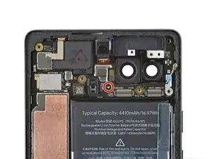
Use a spudger to pry up and disconnect the ultrawide rear camera's press connector.
-
Remove the ultrawide rear camera.
-
-
-
Use a spudger to pry up and disconnect the wide rear camera's press connector.
-
Remove the wide rear camera.
-
-
-
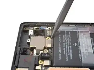
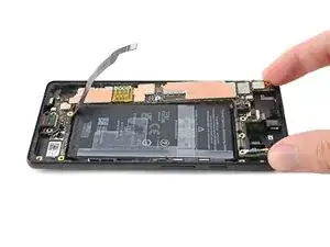
Insert a spudger between the top of the motherboard and the frame, near the front camera.
-
Pry up to lift the motherboard until you can grip it with your fingers.
-
-
-
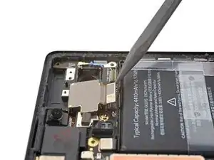
Tilt the top of the motherboard upwards to release its plastic clips.
-
Remove the motherboard.
-
-
-
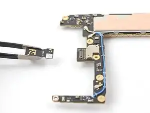
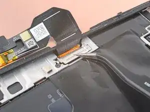
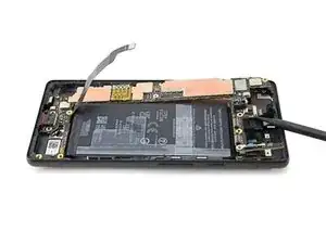
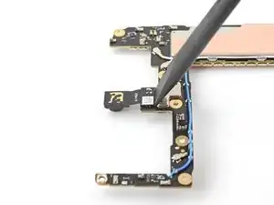
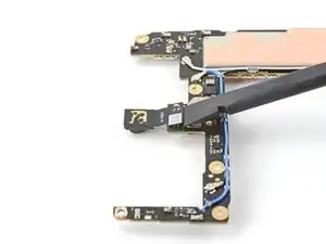
Use a spudger to pry up and disconnect the front camera's press connector located on the bottom of the logic board.
-
Remove the front camera.
-


Compare your new replacement part to the original part—you may need to transfer remaining components or remove adhesive backings from the new part before you install it.
To reassemble your device, follow these instructions in reverse order.
Repair didn’t go as planned? Try some basic troubleshooting, or ask our Google Pixel 6a Answers community for help.
