Introduction

This repair guide was authored by the iFixit staff and hasn’t been endorsed by Google. Learn more about our repair guides here.

Use this guide to replace the charging assembly. The charging assembly contains the USB-C port and is connected to the vibration motor.

  1. wAO2rliBKNjRPNFp
    wAO2rliBKNjRPNFp
    sOF3jgMKtXwTw3QE
    • If your display glass is cracked, keep further breakage contained and prevent bodily harm during your repair by taping the glass. This also makes a smooth surface allowing the suction cup to bond.

    • Apply a suction cup as close to the volume button edge of the phone as you can while avoiding the curved edge.

    • The suction cup will not make a good seal on the curved portion of the glass.

  2. avTQkVCTMJZevgJY
    avTQkVCTMJZevgJY
    dJrwweYej11ijuYM
    txYtFqoGDv4UxBDE
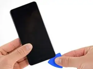
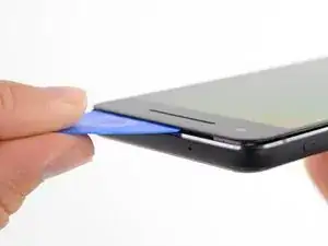
    • Pull up on the suction cup with firm, constant pressure and insert an opening pick between the front panel and rear case.

    • Do not insert the pick deeper than 1.5 mm, or you risk damaging the OLED panel.

    • This requires a significant amount of force and patience. If you have trouble, rock the suction cup and screen to weaken the adhesive, or apply heat with an iOpener, heat gun, or hair dryer.

    • The display panel is fragile. If you plan to re-use your display, take care to insert your tool only as far as necessary to separate the adhesive. Inserting the tool any further can damage the OLED panel under the glass.

  3. RSYXSBeeSGreK1tU
    RSYXSBeeSGreK1tU
    rJRrccJKxCssQRxL
    • In the following steps, extra caution is required in certain areas to avoid damage to the phone:

    • Do not insert the pick more than 9 mm into the bottom edge of the phone. If the pick contacts the folded portion of the OLED panel it can damage the display.

    • Only make very shallow cuts in the upper left corner, prying deeply can damage the front-facing camera.

    • Inserting an opening tool deeper than 1.5 mm into the sides of the device, or 9 mm into the top and bottom can permanently damage the display.

  4. EMmUoacoYJBggeoq
    EMmUoacoYJBggeoq
    aNShcRN3lT1gILvU
    • In the following steps, use the flat of the opening pick, rather than a corner, to cut here. This will help prevent inserting the pick too deeply.

    • Slide the opening pick up the right side of the phone to separate the display adhesive.

    • Take extra care with the side bezels, which are only 1.5 mm deep.

  5. 2ZereWB1RyT1fDqM
    2ZereWB1RyT1fDqM
    QheOxYBPND2qTmEW
    ABqclJOsvBrYbSRi
    • Slide the opening pick around the upper-right corner and along the top edge of the phone.

    • There's a mesh covering the earpiece speaker on the top edge of the screen. If you don’t have a replacement mesh, take care not to damage or lose this component.

  6. CSIHJiCWeWNvyTYT
    CSIHJiCWeWNvyTYT
    6nflAeiavcU2ayr4
    WjQhcowbgPGBLQPx
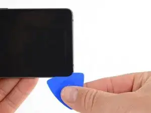
    • Slide the pick around the upper-left corner of the phone and down the left edge of the phone.

  7. tO5kFjHUNBjm4AsA
    tO5kFjHUNBjm4AsA
    WJIBfKgTsge5j4Yi
    FSAYTUP5IIkJH4Mo
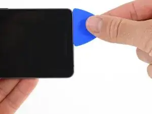
    • Slide the pick around the bottom-left corner and along the bottom of the phone. Keep pick at a slight angle away from the screen to avoid damage to the OLED corners.

    • Take extra care not to insert the opening pick more than 9 mm to avoid damaging the OLED panel.

  8. JqE263rlSCiGMMPx
    JqE263rlSCiGMMPx
    ybiQ4Z6SU44i4TXK
    • Reinsert the pick at the top edge of the phone and gently pry up the display.

    • If the display doesn't readily lift, do some extra prying to separate the last of the adhesive. The adhesive near the upper speaker is thicker than other places.

    • Don't try to fully separate the display yet, as a fragile ribbon cable still connects it to the phone's motherboard.

  9. AWBi6gyoZBNSFCVg
    AWBi6gyoZBNSFCVg
    2YNgAiW26hAJxtF2
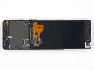
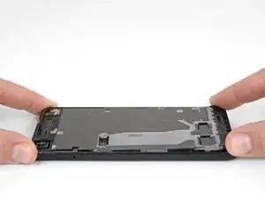
    • Carefully lay the display down on top of the rear case as shown, making sure not to crease or tear the display ribbon cable.

    • Remove the two 4.0 mm T5 Torx screws securing the display cable bracket.

    • Throughout this repair, keep track of each screw and make sure it goes back exactly where it came from.

  10. HuntXSUMrTQOPvUT
    • Remove the display cable bracket.

  11. htMtx16FFYrRZWZB
    htMtx16FFYrRZWZB
    nbBnajSgXNRgYwgn
    • Use the point of a spudger to lift the display cable connector up and out of its socket on the motherboard.

    • Avoid touching the motherboard with the tip of your spudger. The components surrounding the socket are fragile.

    • To re-attach press connectors like this one, carefully align and press down on one side until it clicks into place, then repeat on the other side. Do not press down on the middle. If the connector is misaligned, the pins can bend, causing permanent damage.

    • If any part of your screen doesn't respond to touch after your repair re-seat this connector, making sure it clicks fully into place and that there's no dust or other obstruction in the socket.

    • During reassembly, pause here and replace the adhesive around the edges of the display.

  12. EZUdI4BmuOMhSJui
    • Apply a heated iOpener to the proximity sensor on the top edge of the midframe for two minutes to soften its adhesive.

    Isopropyl alcohol worked quickly for this

    Raquel Smith -

  13. HbJNOR1kLALZjcTd
    HbJNOR1kLALZjcTd
    SrRrbyQwXyPacWk4
    • Slide the point of a spudger under the proximity sensor cable, starting from the side closest to the front-facing camera.

    • Gently lift the edge of the sensor cable until the sensor is perpendicular to the midframe.

    This piece is actually glued down - heat and rubbing alcohol really helped as at first I couldn’t figure out why I couldn’t get it to move.

    Dave Watts -

  14. DF6iCcXDep2Shj2C
    • Peel back the small piece of tape covering the screw below the earpiece speaker. Peel back any tape covering other screws as well.

    • Remove the following screws securing the midframe:

    • Eleven 3.7 mm Phillips screws

    • One 4 mm T5 Torx screw

    • Throughout this repair, keep track of each screw and make sure it goes back exactly where it came from.

    On my Pixel 2, I also had to peel back a small strip of conductive tape that was directly above (and the same kind as) the “screw below the earpiece speaker” mentioned above. It appears to be a ground strap to the assembly underneath.

    Jonathan Dubovsky -

    Me too! Please change the photo?

    Andrew Hoeveler -

    If you don't peel the mesh tape up, it will year. I'm not sure if it plays into the screen potentially not working, but it seems to be a ground for the midframe and the display ribbon has a ground contact to the

    Wesley Krueger -

    Many of the screws would not come out due to the original threadlocker on the threads. I found that if I just kept moving them around with a toothpick, I could get the out. I also had one of those telescoping magnetic bolt grabbers that pulled the screws out.

    John Reagan -

    Would be nice if they included the correct torx bit in the tool kit... mine came with a T2 Torx...pretty useless...managed to get the display ribbon cable free as those screws were surprisingly not super tight - got them with the included Philips bit...pretty F$%^ED right here

    Jens Davidsen -

    @JensDavidsen, I'm sorry to hear that the kit came with the wrong bit. We do everything we can to make sure that our tool kits are kitted correctly. I've gone ahead and forwarded your information over to CS so they can get this fixed for you. In the future, if you have any questions or concerns, don't hesitate to reach out to us directly.

    Kris Rodriguez -

  15. HEw3eLh2pEVebIL6
    HEw3eLh2pEVebIL6
    LCQWWIipK2OVjkmP
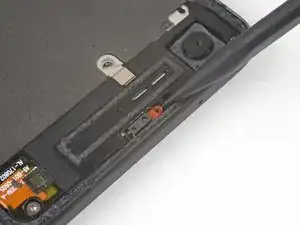
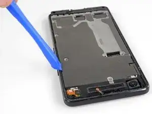
    • Insert an opening tool into the notch in the midframe near the hold button.

    • Pry the midframe up enough to create a gap between it and the phone case. The midframe cannot yet be completely removed.

    This is to pop a securing tab out it's place

    Wesley Krueger -

    On re-assembly make sure the securing tab, near the notch you use to open it, is inserted back under the frame again - this caused me to have to re-open my phone as my screen didn’t sit back down properly after I had put everything back together.

    Dave Watts -

    It is more effort than I anticipated. I really thought I was going to break it, but it was fine.

    John Reagan -

  16. OS6IR34P416u1kUn
    OS6IR34P416u1kUn
    bZXWgUSBDVDpCf1y
    qvUYTFk3VKDRNlOb
    • Lift the midframe up starting from the bottom edge.

    • When the midframe starts to make about a 45° with the rest of the phone, lift the midframe straight up and away from the phone.

    • As you lift the midfame, carefully guide the proximity sensor through the small slot in the midframe.

    While not shown here in the photo, there is a short braided cable between the midframe and the motherboard near the front facing camera that prevents separating the midframe completely (ground?). Be careful not to damage this cable when completing the remaining steps or carefully remove before trying to separate the midframe completely.

    ericdowens -

    As ericdowens says above, there’s a small silver sliver of a connector (next to the front-facing camera). The guides on youtube said it was a grounding wire. This guide doesn’t mention it. Mine broke when I removed the midframe. No big deal. I stuck it back down with some tape when I put it all back together. Phone works fine.

    Alex Lawson -

    I had a heck of a time levering up the midframe. I had popped the side with the opening tool, but the other side was really stuck. I used some alcohol along the edge thinking there was some adhesive. Not sure. I eventually used a dental pick to pop it loose.

    And when reinstalling, don’t forget to move the short braided cable back out of the way so you don’t trap it inside.

    John Reagan -

    STOP! Before you lift the midframe, the ground strap mentioned by ericdowens and Alex Lawson definitely will break if you don’t remove it from the midframe before lifting. I didn’t quite know what they were talking about, so thought I’d look for it as I was lifting the midframe, as I was sure if I was careful I’d spot it before it would break. I was very gentle, and I still broke it before realising what they were talking about. Look for some silver mesh tape on the midframe, near the forward-facing camera, same kind of tape as over the screw shown in Step 14. I’m going to try and carefully tape mine back together as Alex Lawson did, but it will be very fiddly, wish I hadn’t broken it in the first place!

    Jamie Lamb -

    I broke mine... then proceeded to pilfer about 2mm worth of the tape depicted in step 18 because it's a silvery adhesive.

    Jens Davidsen -

  17. ARK3wcDKuwSV4Y4b
    ARK3wcDKuwSV4Y4b
    tV1ItBGOoAQhwkQH
    • Use the flat end of a spudger to disconnect the battery connector.

    This photo and tutorial doesn't show the shielding on the chips of the motherboard. And the glue…My pixel 2 had the volume button ribbon cable glued to the shielding. Carefully pry the cable off. Very carefully slide under it. Maybe use a little heat to soften the glue. You cannot just remove the motherboard with removing the ribbon cable for the volume buttons.

    Austen -

  18. UHNVokwDRm2EZLuL
    UHNVokwDRm2EZLuL
    w4I64vZiMgqsrt1w
    • Use the flat end of a spudger to disconnect the charging assembly connector.

    There is a metal cover not shown here that covers the motherboard, on it the charging assembly is glued with a little adhesive. To remove it apply heat with the iOpener or a heat gun and carefully pull it with an spudger or a tweezer.

    Quique García -

  19. EtJHHXVyBiIvxDWU
    EtJHHXVyBiIvxDWU
    oh5NEsFAOqsDaYdS
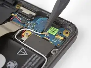
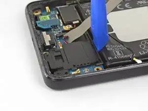
    • Use the point of a spudger to pry the white antenna cable connector straight up and disconnect it from the charging assembly board.

  20. 2sPeuZnDNFGmhFt3
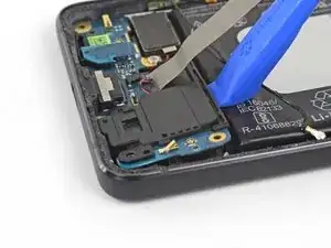
    • Use tweezers to pull the white antenna cable straight up and out of the metal clips on the board and out of the channel on the loudspeaker.

    • Move the cable to the left of the phone to keep it out of the way of the loudspeaker.

    • When reassembling your device, carefully reroute the antenna cable back in place.

  21. VHCWVGx22s44Hfxe
    VHCWVGx22s44Hfxe
    6GLBAxWXiEWw3eYR
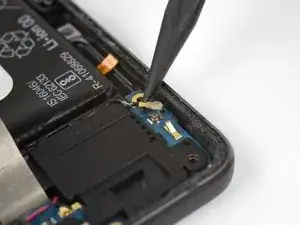
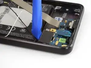
    • Use the tip of a spudger pry the black antenna cable connector straight up and disconnect it.

  22. fFXpX4AmNiPv32YL
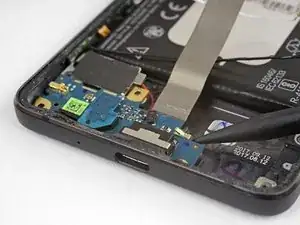
    • Use tweezers to lift the black antenna cable out of its channel on the loudspeaker.

    • Move the cable toward the top of the phone to keep it out of the way of the loudspeaker.

  23. DKa2pAoAlixllCds
    DKa2pAoAlixllCds
    AZHSQxNVBJUolWLh
    kAETIQClHoej6nqn
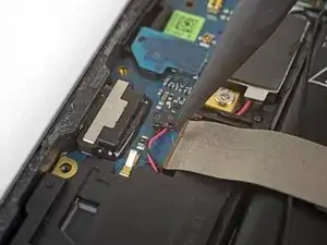
    • Use the tip of a spudger to gently push the speaker cable connector out of its socket horizontally, alternating pushing either side of the connector out a little bit at a time.

    This step is correct but does not explain the design of the socket or the process needed to remove it very well. The two wires enter a socket that has a very thin (you will need a magnifier to see it well) edge. This is what is pulled out horizontally from the circuit board socket. The socket base remains on the board. It would be 2000% helpful if there was a photo showing a close-up of the socket base from the socket itself - together in the same photo. The good news is if you are replacing the charging port, the new board will have a socket base into which you can plug your socket.

    James D Mc Kelvey -

    I agree, broke the base when following the instructions as is but was lucky the new port board has a base

    Sid -

  24. ifTC1T5WQXWRmgpN
    ifTC1T5WQXWRmgpN
    2EfyY1HRAH3HA266
    • Use an opening tool to pry the loudspeaker assembly up slightly from its recess in the phone.

    • Hold the silver charging assembly cable out of the way while you're working, but be careful not to bend it too far or apply too much strain where it connects to the charging assembly.

  25. 15kkBGuNLuBPxdAK
    15kkBGuNLuBPxdAK
    qCCiXsfbfpWYVb3p
    VkRCLS3BOdJxbeah
    • Rotate the top right corner of the loudspeaker toward the top of the phone while sliding the whole assembly to the right.

    • Remove the loudspeaker.

  26. k5FschrgjaINXcfZ
    • Remove one 2.4 mm Phillips screw.

  27. HHcBqUlAXK2dIX3D
    HHcBqUlAXK2dIX3D
    lkWQiTtnaAJ2aTtS
    • Use an opening tool the gently lift the vibration motor and separate it from the adhesive holding it to the phone.

    • Do not try to remove the motor—it's still attached to the charging assembly.

  28. ULCSZSpByTCSdMh3
    ULCSZSpByTCSdMh3
    kxiEoXfbyNHYEXXd
    • Use the point of a spudger to lift the top of the charging assembly away from the phone.

    • Do not completely remove the charging assembly yet. It is still attached to the vibration motor.

  29. d5U4CftCiH26TZcT
    • Make sure the vibration motor is not adhered to the phone, then gently lift the charging assembly out of the the phone, lifting the motor out at the same time.

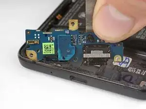
    • Remove the microphone board and transfer it to the new charging assembly.

    • If you wish to remove the vibration motor, you have to desolder its wires from the charging assembly board.

    In the last step, the microphone board is attached to the charging assembly and needs to be removed and placed on the new assembly when replacing.

    Adam Wellner -

    I wish I could highlight your comment or get the original author to point this out in an image. I didn’t check this the first time through and had to pull the phone back apart to add the mic onto the new charging assembly.

    (My mistake for not checking the boards against each other carefully - all other instructions were so thorough, I didn’t feel the need at the time to verify.)

    Aubrey Apperson -

Conclusion

Compare your new replacement part to the original part—you may need to transfer remaining components or remove adhesive backings from the new part before installing.

To reassemble your device, follow the above steps in reverse order.

Take your e-waste to an R2 or e-Stewards certified recycler.

Repair didn’t go as planned? Check out our Answers community for troubleshooting help.

Adam O'Camb

Member since: 11/04/15

172888 Reputation

3 comments

I’m fairly disappointed with this. It didn’t say that the microphone chip had to be transferred to a new part. This caused me to take this phone apart twice.

fatkidadventure -

In step 11, make sure to list the connector from the side. I just rendered my phone useless by damaging one of the micro-components at the bottom of the connector socket. :(

Sebouh -

Is the charging assembly PCBA really responsible for battery charging?

Or is it just supplying the 5V from the charger thru the flex to the motherboard, which is in fact responsible for the charging?

There are additional "data" pins on the battery, which I suppose are also used during charging to report battery temperature etc., but these pins are not directly connected to the flex connector.

So I think that the motherboard is responsible for charging.

My phone is not charging, but i can measure the 5V from the USB on the motherboard connector at the end of the flex. Will it help to change the charging assembly?

Kib Bul -