Introduction
This guide will show you how to repair a DualShock 4 with a not working button. This guide is ONLY for JDM-001 / JDM-011 Motherboard models. (CUH-ZCT1 Controllers)
- Before ordering the replacement part, open up your controller using the teardown guide to determine your motherboard model No. (usually behind the battery tray).
- I do not have any responsibility for ordering the wrong model. I warned you!
-
-
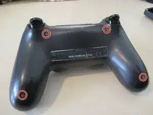
Unscrew these 4 PH0 Screws to open the back cover.
-
Carefully pry around the cover with a spudger. Pull the back part to open the enclosure.
-
Disconnect the light bar ribbon cable.
-
-
-
Disconnect the battery connector and remove the battery.
-
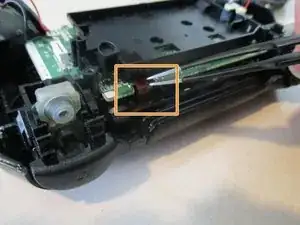
And the touch bar cable. Push the cable carefully through the small hole in the plastic midframe.
-
-
-
Remove the lonely, PH1 screw holding the motherboard and the midframe.
-
Remove the front cover from the midframe. If it gets stuck, you may need to jiggle the joysticks.
-
-
-
Starting from the bottom, carefully remove the board from these 4 latches. It might also get caught on the bottom of the speaker grille.
-
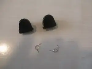
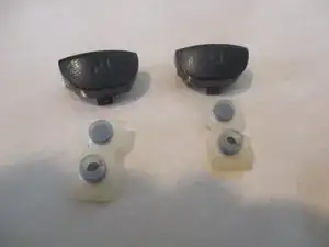
Then, remove the bumper buttons and the contact pads outward from for them and the triggers. A slight force must be applied.
-
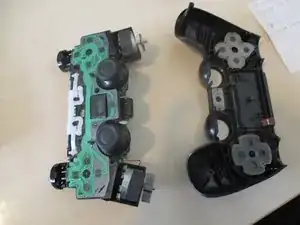
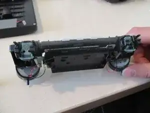
The top of your controller should now look like pic. 3 Then, unlatch the board from there as well
-
To be continued...
-
-
-
Now that your controller looks something like pic 1, open the midframe Partially.
-
Remove the two more latches on the sides of the contact pins.
-
Pull the board out carefully.
-
-
-
Get your new button board and follow the steps in reverse order to reassemble your device. If you need help re installing the trigger buttons (trust me, it is hard to do so) follow this guide: PS4 Dualshock 4 trigger reassembly
-


To reassemble your device, follow this guide: PS4 Dualshock 4 trigger reassembly

8 comments
pieces of $@$*, it uses 00 not 0, you made me buy a useless screwdriver
I am sorry for your experience but a PH0 screwdriver worked just fine for me. If it doesn’t quite work for you, try the rubber band trick: place a thin and wide rubber band on the screw and squish it with the screwdriver. Also, it’s not useless, I have bought so many things calling them that and wouldn’t you know it one day I was so grateful that I had these lying around. Happy repairing Tar!
Devnol -
I’ve changed two flex boards from two different sellers, and I keep having a battery drain of about 25mA after i installed them. The battery drain is not present with the original flex board, any ideas?
Ok no, little update. the battery drain is present even if I disconnect the flex board, the touch connector and the led . It’s something on the main board I think, but I can’t figure out what is it. Is there some insulation that I may have lost when changing the flex board the first time?
That sounds really weird. I don’t remember any insulation on this specific model of controller. I don’t have this anymore as it was a repair for a friend and I also hadn’t noticed or measured such a drain.
Devnol -
The only other thing I can think of is a failure on one of the components soldered on the main board, but 20mA in standby condition are VERY high!