Introduction

Follow this guide to replace the light guide on your Sony DualSense controller.

Note: This guide is for current DualSense controllers with FCC IDs that end with A. Check the back of your controller to verify your model. If yours ends in a 1, it is an early model and there will be internal differences. Follow these guides for the earlier version.

  1. guhDdaTLO4Lx2TSt
    guhDdaTLO4Lx2TSt
    lRfON2tMHbYtvv3T
    • Disconnect and power down your controller before you begin.

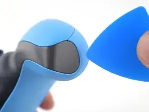
    • Insert an opening pick underneath the middle trim at the bottom-right corner of the controller to release the clips securing it to the case.

  2. KH36rgc41xkkIxEt
    KH36rgc41xkkIxEt
    UHgHxxDZK6uAadgL
    YCZY4rdKhkAMTZ62
    • Slide the opening pick along the lower-right edge of the middle trim to release the clips securing it to the case.

  3. POGlGjVFG32wJM2y
    POGlGjVFG32wJM2y
    PwStjKyYwXi1TP5q
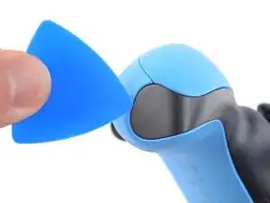
    • Insert an opening pick underneath the middle trim at the bottom-left corner of the controller to release the clips securing it to the case.

  4. pXLCWFnCEuauqlKC
    pXLCWFnCEuauqlKC
    qdiJcNkOKbKphjJd
    gkLGOOWGftSaTGuV
    • Slide the opening pick along the lower-left edge of the middle trim to release the clips securing it to the case.

  5. AB2xCYOXsbgPYry2
    AB2xCYOXsbgPYry2
    3Khr4r3J6arnKYaV
    CgyN41nIJb3FiQSj
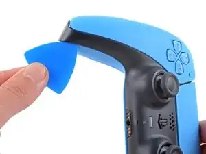
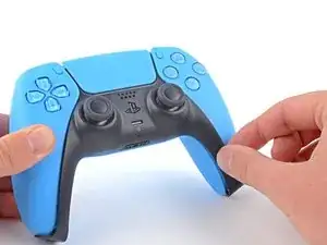
    • Use your fingers to lift up the bottom edge of the middle trim to release the remaining clips.

    • Lift the middle trim over the joysticks to remove it.

    • During reassembly, position the middle trim into place and press along all edges to engage the clips securing it to the controller.

  6. UTnysFXrcZOXyN6b
    UTnysFXrcZOXyN6b
    gCEpcBW2RIqwfE3g
    UfskjjRq6Xc5sN2T
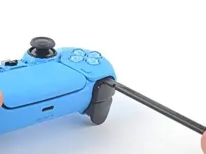
    • Insert the flat end of your spudger into the gap above the L1 button.

    • Cover the button with your thumb to prevent it from ejecting across the room.

    • Pry the spudger upward to remove the L1 button.

  7. DOGoFB2gdmebKksg
    DOGoFB2gdmebKksg
    a2OZYntXvJ5jEqwl
    XZM6oSOTggRpulT6
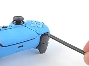
    • Insert the flat end of your spudger into the gap above the R1 button.

    • Cover the button with your thumb to prevent it from ejecting across the room.

    • Pry the spudger upward to remove the R1 button.

  8. NZyynHfafAxnDJyk
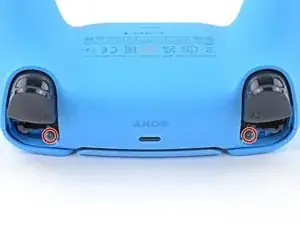
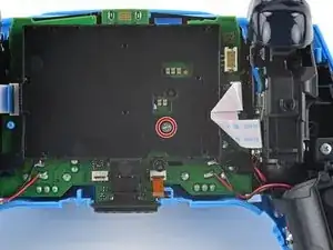
    • Use a Phillips screwdriver to remove the two 6.5 mm screws securing the bottom corners of the lower case.

  9. smAEGEk5WFdOafDe
    • Use a Phillips screwdriver to remove the two 6.5 mm screws behind the L1 and R1 buttons.

  10. KlxNTlBTTfFMuoPL
    KlxNTlBTTfFMuoPL
    euRWr4gYHKkFKvkN
    YGhW3IgpAKVBmarb
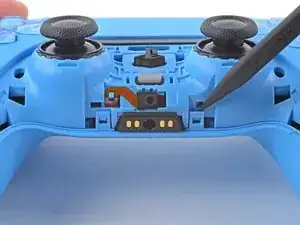
    • Use the pointed edge of a spudger to unclip the two clips on either side of the headset jack.

  11. xjWsqFGNDLDLMbkS
    xjWsqFGNDLDLMbkS
    R43JFU2tjntM3GOJ
    • Use your hands to carefully pull the rear case off of the controller.

    • During reassembly, make sure the red and black vibration motor wires are not pinched between the front and rear case.

  12. MUHdthfOoyldBVFr
    MUHdthfOoyldBVFr
    BQpL6myW2JRojkMo
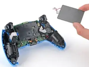
    • Lift the battery out of its bracket and reposition it to the right for better access to the battery connector.

    • Don't strain the battery cables.

  13. WfRwBl31EDPRpSGo
    WfRwBl31EDPRpSGo
    NxOiZWbvbAOk6Q64
    • Use a pair of tweezers or your fingers to disconnect the battery from the motherboard.

    • Don't pull on the wires to disconnect the battery.

  14. DLcICSfOGofUvx6a
    • Remove the battery.

  15. SauAEOZxj4FCS6NM
    SauAEOZxj4FCS6NM
    KDoPLAYcFsP5ueyb
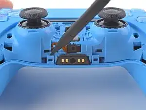
    • Use the pointed end of your spudger to remove the lower microphone from its bracket next to the battery.

    • During reassembly, make sure the end of the microphone's ribbon cable is slotted into the bracket.

  16. v4nWXxvIlhysHlLy
    v4nWXxvIlhysHlLy
    43K5VZLmUlUGTBXM
    • Grab the lower microphone ribbon cable pull tab with your fingers or a pair of tweezers and disconnect it from the motherboard.

  17. TYxs5oRu2B5aAtxp
    • Use a Phillips screwdriver to remove the 6.5 mm screw securing the battery bracket.

  18. xlXMna1BPmWLfKCA
    xlXMna1BPmWLfKCA
    TaW3YP1JZthaEuCN
    • Lift the battery bracket off of the motherboard.

  19. hlS5jSTJlyd21Dux
    hlS5jSTJlyd21Dux
    1u6l2dySSGgK1fPi
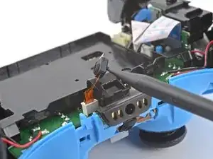
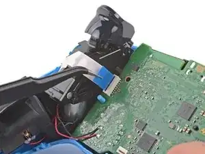
    • Grip the right trigger assembly cable with a pair of tweezers or your fingers and disconnect it from the motherboard.

    • Use the pull tab to disconnect the cable. Don't pull on the cable itself.

    • Don't completely remove the ribbon cable yet.

  20. HNXlyG2tTg3BpVBA
    HNXlyG2tTg3BpVBA
    HLH5oEnH5vWTCfY6
    • Grip the right trigger assembly cable with a pair of tweezers or your fingers, and disconnect it from the trigger assembly.

    • Use the pull tab to disconnect the cable. Don't pull on the cable itself.

    • Remove the ribbon cable.

  21. HDWPjnXLgdqSMQor
    HDWPjnXLgdqSMQor
    laXRqreMTfEVUj4y
    • Grip the left trigger assembly cable with a pair of tweezers or your fingers to disconnect it from the motherboard.

    • Use the pull tab to disconnect the cable. Don't pull on the cable itself.

    • Don't completely remove the ribbon cable yet.

  22. ybMtetJ23SIypkFk
    ybMtetJ23SIypkFk
    UPBCTR4HNO6g4Aym
    • Grip the left trigger assembly cable with a pair of tweezers or your fingers to disconnect it from the trigger assembly.

    • Use the pull tab to disconnect the cable. Don't pull on the cable itself.

    • Remove the ribbon cable.

  23. aHgoOpyh14SgWJML
    aHgoOpyh14SgWJML
    Co4QFEZsSk5HmTSN
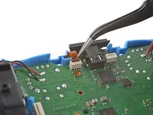
    • Use a pair of tweezers or your fingers to disconnect the upper microphone from the motherboard.

    • Use the pull tab to disconnect the cable. Don't pull on the cable itself.

  24. 6yoTmH3DGDjJN1T5
    6yoTmH3DGDjJN1T5
    YWwUpnVcRcpnoIm2
    • Use a pair of tweezers or your fingers to disconnect the touchpad cable from the motherboard.

    • Use the pull tab to disconnect the cable. Don't pull on the cable itself.

  25. IB3IHd151RUPhUqV
    IB3IHd151RUPhUqV
    TccAbvZvIpLAERIJ
    2xHcMnrLJn3PS5fu
    • Carefully guide the joysticks through the front case and lift the motherboard out.

    • Don't strain the four soldered wires tethering the motherboard to the vibration motors.

  26. VYYRxEAoslcsEiwO
    VYYRxEAoslcsEiwO
    m5Z5fXfZLyBbx3AX
    hrTQVjgHHGXZpq4P
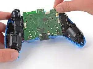
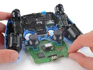
    • Use the pointed end of your spudger to lift the center of the light guide out of the controller.

    • Remove the light guide.

Conclusion

To reassemble your device, follow these instructions in reverse order.

Take your e-waste to an R2 or e-Stewards certified recycler.

Repair didn’t go as planned? Try some basic troubleshooting, or ask our Answers community for help.

Sam Omiotek

Member since: 25/02/19

53290 Reputation

0 comments