
Introduction
Here I will go through the steps to disassemble the Ender 3 v2 in preparation for the BLV upgrade kit.
-
-
Remove the 2x M3x6 button head screws with a 2mm allen wrench. to remove the hotend cover assembly.
-
Remove the original hotend by removing the 2x M3x12 button head screws with a 2mm allen wrench.
-
If equipped, remove the BLTouch/CRTouch.
-
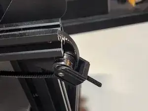
Remove the belt tensioner housing by removing the tensioner knob and the M4x16 countersunk screw with a 2.5mm allen wrench.
-
-
-
Remove the belt by unhooking it from the bottom if the X carriage plate and pulling it out.
-
To gain access to the M3 screws for the X stepper remove the QR sticker.
-
Disconnect the stepper motor and endstop cables.
-
Remove the 4x M3x40 countersunk screws using a 2mm allen wrench. Remove the X stepper cover and stepper motor.
-
Remove the X carriage plate by using a 10mm wrench to loosen the eccentric nut on the bottom of plate and slide it off the 2020 extrusion
-
-
-
Disconnect the extruder stepper cable.
-
Remove the 1x M3x20 socket head screw with a 3mm allen wrench.
-
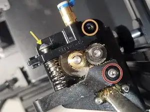
Remove the 1x M3x10 button head screw with a 2mm allen wrench. Remove the extruder tensioner arm.
-
Remove the 1x M3x10 button head screw with a 2mm allen wrench.
-
Remove the 1x M3x8 countersunk screw with a 2mm allen wrench. Remove the extruder stepper and set aside.
-
-
-
Disconnect the Z stepper cable.
-
Remove the leadscrew by loosening the bottom M3 screw with a 2.5mm allen wrench.
-
Remove the stepper motor and mount by removing the 2x M4x18 countersunk screws with a 3mm allen wrench.
-
Loosen both eccentric nuts.
-
To remove the left Z axis plate remove the 3x M5x40 button head screws and 2x M5 locknuts to separate the Z brackets.
-
Remove the 2x M4x16 button head screws with a 2.5mm allen wrench to remove the Z bracket off the 2020 extrusion.
-
On the right side bracket remove the remaining M4x16 button head screw with a 2.5mm allen wrench to separate the right Z axis plate from the 2020 extrusion.
-
-
-
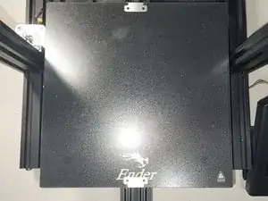
Unclip the glass bed clips and remove the glass.
-
Remove the 4x M4x30 countersunk bed screws, 4x bed springs and 4x leveling wheels.
-
Loosen the Y axis tensioner and remove the belt by unhooking it from the bottom of the Y plate.
-
Remove the Y axis tensioner by removing 2x M5x12 button head screws with a M3 allen wrench.
-
-
-
To remove the Y carriage, loosen the 2x right side eccentric nuts with a 10mm wrench and slide the whole Y carriage out of the 4040 extrusion.
-
I found out after this point but I ended up having to replace the Y stepper mount because it got a "little" warm.
-
Remove the X stepper cable and Y endstop cable.
-
To remove the Y stepper motor remove the 2x M5x12 button head screws on the bottom of the stepper mount.
-
-
-
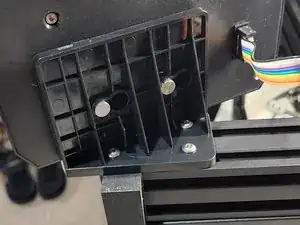
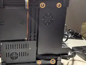
On the top of the electronics enclosure remove the 2x M3x6 button head screws with a 2mm allen wrench.
-
On the bottom remove the 3x M3x6 button head screws with a 2mm allen wrench.
-
Now is also a good time to cut that zip-tie.
-
Remove the 2x M5x12 button head screws on the front of the extrusion was a 3mm allen wrench.
-
Disconnect the wires as needed to remove the mother mounting plates.
-
Remove the 3x M4x10 button head screws with a 2.5mm allen wrench removing the LCD and mounting bracket.
-
-
-
It's a good idea to remove the PSU entirely. Remove the 4x phillips screws.
-
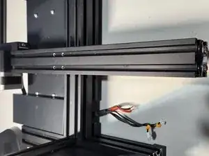
This is how your frame should look at this point.
-
If you're going to be using my SKR3 EZ mount you will need to tap these 2 holes on the right front side of the 4040 extrusion with a M5 tap.
-


To reassemble your device, follow these instructions in reverse order.