
Introduction
Tools
-
-
With a Phillips 0-bit screwdriver, remove six 13.5 mm screws located on the edge of the panel.
-
With a Phillips 0-bit screwdriver, remove five 6.4 mm screws located on the edge and center of the panel.
-
-
-
With a Phillips 0-bit screwdriver, remove eight 5.0 mm screws on the silver brackets
-
With a Phillips 0-bit screwdriver, remove two 5.0 mm screws holding the edge of the fans in place
-
-
-
Gently remove all power cables connecting the fans to the motherboard.
-
Once all cables and screws are removed, carefully lift up and remove the fans and heat sink
-
-
-
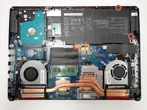
With a Phillips 0-bit screwdriver, unscrew four 5.0 mm screws.
-
Disconnect the primary connector cable located at the bottom left and carefully remove the module.
-
-
-
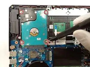
With a Phillips 0-bit screwdriver, unscrew four 5.0 mm top screws holding the hard drive in place.
-
Pinch the top left corner with your finger and slide the harddrive out of its casing.
-
-
-
With a Phillips 0-bit screwdriver, unscrew two 5.0 mm screws holding SSD down to the motherboard on the right side of the board
-
Slide module out of protective casing to remove piece.
-
-
-
On the center of the motherboard, lightly push down on the metal clamps holding down the RAM module.
-
Once unclipped, carefully remove the module and secure in a safe place.
-
-
-
With a size 0 Phillips screwdriver, unscrew three center 5 mm screws securing the board in place.
-
Carefully lift the board and place in a safe area.
-
-
-
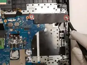
With a size 0 Phillips screwdriver, unscrew two 5 mm screws holding the trackpad in place located at the bottom of the trackpad.
-
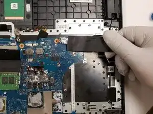
Carefully unclip the connector base to remove the two touchpad cables.
-
Remove the trackpad by sliding forward and lifting up.
-


To reassemble your device, follow these instructions in reverse order.
